Written on: October 9, 2023 by Timmie McElwain
Part 14, from the Sep/Oct 2023 Indoor Comfort.
Parts 1 & 2, from the Jul/Aug and Sep/Oct 2021 Indoor Comfort can be found here.
Part 3, from the Nov/Dec 2021 Indoor Comfort can be found here.
Part 4, from the Jan/Feb 2022 Indoor Comfort can be found here.
Part 5, from the Mar/Apr 2022 Indoor Comfort can be found here.
Part 6, from the May/Jun 2022 Indoor Comfort can be found here.
Part 7, from the Jul/Aug 2022 Indoor Comfort can be found here.
Part 8, from the Sep/Oct 2022 Indoor Comfort can be found here.
Part 9, from the Nov/Dec 2022 Indoor Comfort can be found here.
Part 10, from the Jan/Feb 2023 Indoor Comfort can be found here.
Part 11, from the Mar/Apr 2023 Indoor Comfort can be found here.
As we look at modern systems and what specific problems they present, it’s important to understand the basic fundamentals associated with these systems.
Most of our modern heating equipment in some way or another involves electronics; along with the use of electronics is the use of flame rectification as a safety and flame-proving system. It doesn’t matter if it is a forced warm air furnace or a forced hot water boiler; the same basic system is used to perform safe ignition, and then consistent operation, throughout the entire call for heat.
There are, however, different ways it is applied—from intermittent pilot application to direct spark ignition and including hot surface ignition. Each system has its own distinct advantages and problems. Next in this series of resolving burner issues related to these systems, we offer corrections and diagnostics to help solve those problems.
We will start with the basics and go into operation, typical problems, diagnosis, troubleshooting procedures and a final solution to a particular problem. It can be easy to jump to conclusions and change parts until you hopefully solve the problem. That is, however, time-consuming and costly.
I invite you to visit our Facebook page, Timmie’s Tips On Gas, I look forward to seeing you there.
We are presently doing a series on Honeywell Smart Valve and will continue to cover Smart Valve Generation III, with step-by-step troubleshooting of these controls.
Gas Valve/Induced Draft Fan/Pressure Switches
The Gas Valve is connected to the combustion chamber through a series of tubing connections, which include the Induced Draft Fan, the Low Fire Pressure Switch and the High Fire Pressure Switch.
The gas valve has a knurled fitting at what would be the normal regulator vent to atmosphere. The knurled fitting is for the tubing to fit over; the valve is then connected to the combustion chamber so that the valve senses, not room pressure, but combustion chamber pressure. The two pressure switches are set up to be differential switches, which must sense a certain differential pressure in order for them to close. The differential pressure for the Low Fire Switch is .58″ W.C. and the High Fire Switch is 1.38″ W.C.
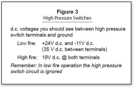
Looking at the diagram shown in Figure 1, when the initial W1 call for heat takes place, the SmartValve sends 120 VAC from P1-4 to C3-2 then from C3-1 on the Inducer In to Ind In on the EFT. Then 120 VAC is sent from Ind High on the EFT to the inducer, which comes up to high speed. This creates sufficient differential pressure to cause both Low Fire and High Fire pressure switches to close. The High Fire pressure switch will then pass DC voltage to the two-stage (black) solenoid, which will cause it to increase the gas pressure in order to reach High Fire setting. The complete tubing connection set-up is shown in Figure 1. The DC voltages expected are illustrated in Figure 3.
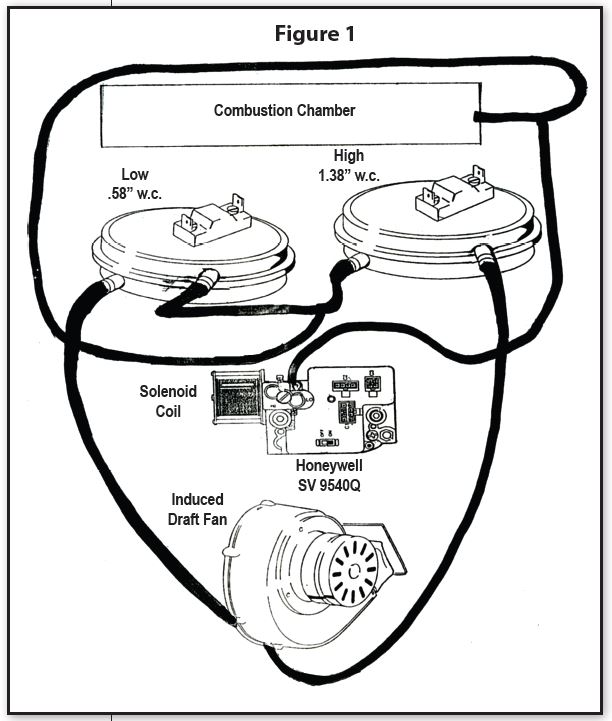
Figure 1 also shows the wiring diagram for this system. Prior to the main burner turning on, a three-second pre-purge will occur; then the igniter will light the pilot and the flame will be proved from the sensor. If the microamp signal is 1.5 microamps or greater, then the valve will be energized through the limit switch, rollout switch and low-pressure switch. The burner will turn on at High Fire setting and run until the delay is satisfied; the system will then shut down the DC signal to the solenoid and the system will go to Low Fire. The inducer will be running at low speed and the DATA signal from the SmartValve will be sent to the ST9162 EFT board and the fan [on delay] will start. In 30 seconds, the system fan will come on at low speed and the burner will be at Low Fire. If there is a subsequent “R” to “W2” High Fire call, then the DC signal will be sent to the two-stage solenoid due to the ST9162 sending a 120 VAC signal from the board to the inducer. Additionally, it will go up to high speed closing the high pressure switch. The system fan will then also go to high speed.
When the thermostat is satisfied, the power to the inducer will be shut down after a five-second post-purge. Timed from the gas valve de-energizing, the low heat fan speed de-energizes after the selected heat fan delay “off” time expires.
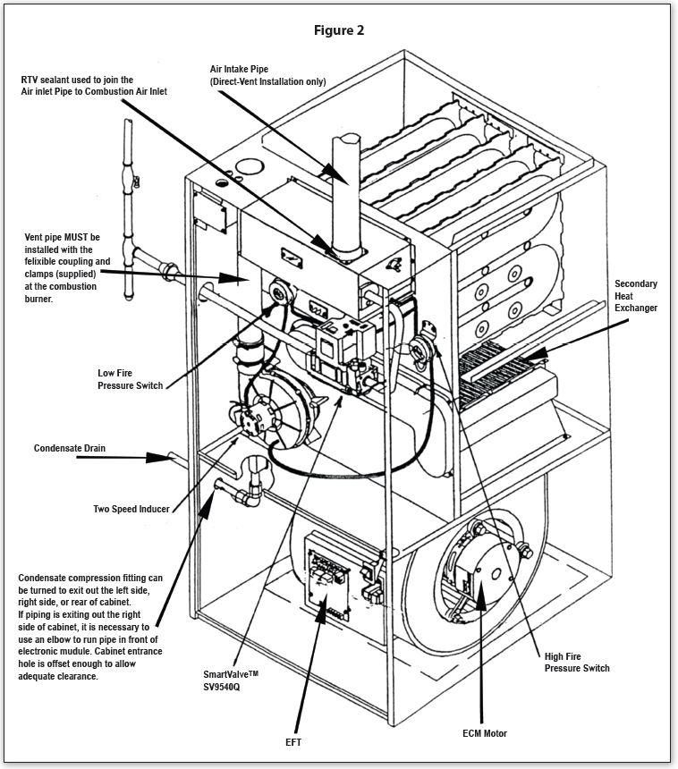
Figure 2 show various components and their location on the furnace. The condensing principle is accomplished by causing the water (vapor-laden) products of combustion to be drawn into the secondary heat exchanger by the inducer fan. This will, with the blower blowing across the heat exchanger, cause the vapor to condense; the latent heat will be drawn from it and then the air flow will continue to pass through the primary heat exchanger, picking up even more heat. The condensate is then dumped out of the condensate drain typically either into a neutralizer, a condensate pump or a combination of both. The electronically commutated motor (ECM) allows for variable speeds to control the cubic feet per minute (CFM) flow in order to cut down on the possibility of blowing cold air. The ECM motor is controlled by signals from the EFT board. Figure 2 further shows the location of the high and low-pressure switches, along with the two-speed inducer.
This system uses a DC blower called GE ECM motor. There will be a separate column on ECM motors, so we will be brief in our discussion here. This is not a regular 120 VAC motor that many may be familiar with, so special instructions are necessary in order to properly diagnose problems within this system.
The Modulating Furnace ECM Blower Motor
Motor Operation
The modulating furnace uses the GE ECM motor. The motor is a DC motor. Line voltage AC power is converted to DC by an inverter inside the motor electronics control. DC voltage powers the motor stator; therefore, it is a synchronous motor. Since it is a brushless motor, there are no brushes to wear out and it makes minimal noise.
The rotor uses a permanent magnet. This eliminates almost all rotor losses found on permanent split capacitor (PSC) induction motors. In fact, the magnetic pull can be felt when spinning the rotor by hand.
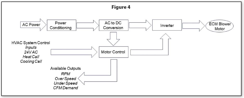
The motor has two inputs. One is 120-volt line power. This motor must be powered continuously with line voltage. It also has a 24-volt power input. Figure 4 shows how power flows to the ECM motor electronics, how that power flows to the blower motor and how the motor electronics send a signal back to the integrated furnace control board.
The airflow through the duct work is varied to meet the load demand. Airflow as low as 300 CFM can be achieved by the response of the brushless permanent magnet variable speed blower motor.
The ECM motor is wired from the 120 VAC source and the feed from the six-pin connector on the ST9162 EFT. Dual in-line package (DIP) switches must be set up at the time of installation. DIP switch settings will be covered in a future column.
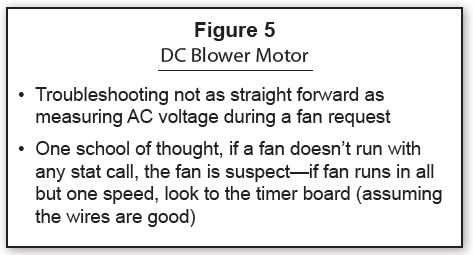
One of the things to consider when diagnosing problems with the ECM motor is that, if the fan does not run on any thermostat call, then the fan is suspect. On the other hand, if the fan runs on all but one speed, then one would suspect the timer board. A quick test to see if the fan will run is to pull a wire off of one of the limits; this should cause the fan to turn “on” (see Figure 5).
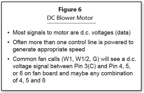
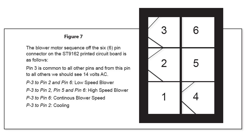
The six-pin connector from the EFT board can be checked for proper voltage (Figure 6). The tests are done as AC tests, looking for around 14 VAC. The #3 pin is the Common Pin; Figure 7 shows the Common Pin relationships for various applications. ICM