Written on: June 13, 2022 by Timmie McElwain
Part VI, from the May/Jun 2022 Indoor Comfort
Parts I & II, from the Jul/Aug and Sep/Oct 2021 Indoor Comfort can be found here.
Part III, from the Nov/Dec 2021 Indoor Comfort can be found here.
Part IV, from the Jan/Feb 2022 Indoor Comfort can be found here.
Part V, from the Mar/Apr 2022 Indoor Comfort can be found here.
As we look into some more modern systems and what specific problems they present, it is important to understand the basic fundamentals associated with these systems. Most of our modern heating equipment in some way or another involves electronics and the use of flame rectification as a safety and flame-proving system.
It doesn’t matter if it is a forced warm air furnace or a forced hot water boiler—the same basic system is used to perform safe ignition followed by consistent operation throughout the entire call for heat.
There are, however, different ways the system is applied from intermittent pilot application to direct spark ignition and including hot surface ignition. Each has its own distinct advantages and problems. We’ll now attempt to resolve those burner problems related to these systems, as well as offer corrections and diagnostics.
We will start with the basics and then continue to operation, typical problems, diagnosis, troubleshooting procedures and a final solution to a particular problem. It’s easy to jump to conclusions with these systems and just change parts to hopefully solve a problem. That is, however, time-consuming and costly.
I invite you to visit our new Facebook page Timmie’s Tips on Gas, I look forward to seeing you there
We are presently doing a series on Honeywell SmartValve™. In this article, we will cover the Smart-Valve™ being used in a Forced Warm Air System. The next article will cover SmartValve™ with a Forced Hot Water System.
Troubleshooting electronic system
There are many different systems in use today on both Forced Warm Air and Forced Hot Water Systems. Knowing how to diagnose and troubleshoot these systems is something everyone needs to be able to do. There are some basic steps to follow.
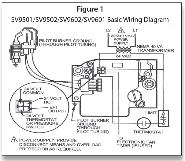
Figure 1 is a basic diagram of a SmartValve™ hookup; we will be going much deeper into the process of diagnoses than this diagram will allow.
One of the first things to know in order to properly troubleshoot a system is the sequence of operation. If you do not know how it is supposed to work, then how will you be able to fix it? In this segment we are going to look at a Forced Warm Air System.
This particular system is composed of a Honeywell SmartValve™ Generation I SV9500/9600 with a Honeywell Electronic Fan Timer ST9120A, B or C. Using the diagram shown in Figure 2 we will walk through a sequence of operation on this system.
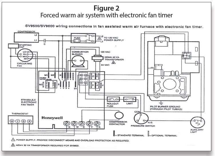
It is interesting to note that modern systems all come with wiring diagrams, both connection diagrams and ladder diagrams, trouble trees, and in some cases we even have diagnostic LEDs to help us find the problems. These, along with a written-out sequence of operation, should make our jobs easier.
The diagram shown in Figure 2 is for a Forced Warm Air System; it shows some air conditioning components, which will not be covered in this instruction.
Sequence of operation
The sequence of operation is as follows:
1. There is 120 VAC fed to terminal S1 on EFT—Neutral wire to N1.
2. 120 VAC is fed from terminal S2 to the primary of a 24 VAC transformer—N4 is neutral. In order to be able to more easily follow this sequence, Figure 3 will illustrate pin numbers and shape of pins for the ST9120.
3. The secondary of transformer goes to X (hot) C (common) Note: on some EFTs, there is a feed from X–4 and C–2 on 6-pin connector.
4. There is an un-interrupted 24 VAC from X and C to SmartValve™ or from pin 4–24 V AC (Hot) to Pin 2–24VAC (common).
5. When thermostat calls for heat R to W
a. 120 VAC is fed out of DI (draft inducer) to combustion blower neutral to N3.
b. The combustion air blower will cause the pressure switch to make COM to NO.
c. 24 VAC out from X to Pin 1 on 6-pin connector.
d. Pin 1 through limit and roll out switch to pin 6 to R (thermostat) through printed circuit board.
e. R to thermostat back to W to pin 3 on 6-pin connector.
f. Pin 3 to pressure switch and auxiliary limit to thermostat terminal on SmartValve™.
6. SmartValve™ is powered 24 VAC to the igniter, igniter glows and lights pilot gas—pilot proves back on clear (or sometimes black) wire a .3 microamp signal or greater. The main valve opens and lights from pilot burner. At this time, a data signal is superimposed on a voltage signal and fed to the EFT pin 5 on 6-pin connector.
7. Different ST9120 EFT boards will have dip switches for fan delay on and fan delay off (three dip switches) or just fan off delay (two dip switches). The 2-dip switch model has a fixed fan on time of 30 seconds. The 3-dip switch model has fan on times of 30 or 60 seconds. The off time on both can be 60, 100, 140 or 180 seconds. The data signal back to the EFT will trigger the fan on timing.
8. The fan comes on and runs until the thermostat is satisfied. Depending on the connection at the motor the fan will run on low, medium low, medium high or high speed. For heating, the HEAT terminal on EFT should be connected to low on motor and back to N2 on EFT. (Note: M1 and M2 on EFT are for unused motor leads).
9. When the thermostat is satisfied, the circuit to EFT is broken, the SmartValve™ shuts down and the fan-off delay starts (based on dip switch settings).
10. Fan shuts off—waiting for next call for heat. This completes the sequence of operation. It is the first step in troubleshooting and must be understood in order to further grasp how the system operates.
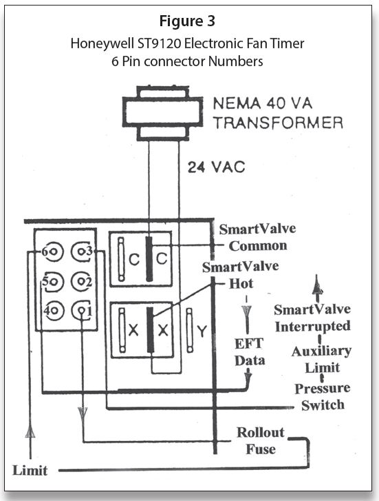
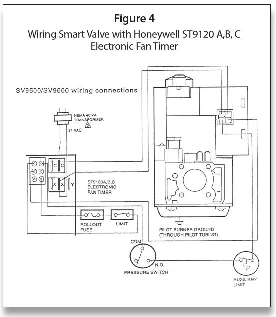
Figure 4 shows how the sequence takes place coming off the ST9120 control. It should be noted that the Auxiliary Limit is often difficult to find on Forced Warm Air Systems. It is sometimes located on the outlet side of the unit. Its purpose is to protect the heat exchanger from becoming damaged by excessive temperature. The whole idea of higher efficiency systems is to hold as much heat in the unit versus losing heat up the vent. This is why the system fan has to come on so soon.
Educational opportunities
Finally, I love to teach and would love to have you join us for some training. We conduct seminars on the following topics and many others:
One-Day Course:
• Powerpile Systems
Three-Day Course:
• Combustion Testing Design Gas Equipment
• Conversion Burners
Four-Day Course Designed for Your Specific Need:
• Modulating/Condensing Boilers
Five-Day Course:
• Fundamentals of Gas
• Circuitry & Troubleshooting
• Hydronic Controls
• Electric Ignition Systems
• Advanced Electric Ignition Systems
For more information, Tel: 401-437-0557; E-mail: timmcelwain@gastcri.com or write to: Gas Appliance Service Training & Consulting, 42 Village Dr., Riverside, RI 02915. ICM