The Gas Side— Honeywell SmartValves™: Part 13
Written on: August 7, 2023 by Timmie McElwain
Part 13, from the Jul/Aug 2023 Indoor Comfort.
Parts 1 & 2, from the Jul/Aug and Sep/Oct 2021 Indoor Comfort can be found here.
Part 3, from the Nov/Dec 2021 Indoor Comfort can be found here.
Part 4, from the Jan/Feb 2022 Indoor Comfort can be found here.
Part 5, from the Mar/Apr 2022 Indoor Comfort can be found here.
Part 6, from the May/Jun 2022 Indoor Comfort can be found here.
Part 7, from the Jul/Aug 2022 Indoor Comfort can be found here.
Part 8, from the Sep/Oct 2022 Indoor Comfort can be found here.
Part 9, from the Nov/Dec 2022 Indoor Comfort can be found here.
Part 10, from the Jan/Feb 2023 Indoor Comfort can be found here.
Part 11, from the Mar/Apr 2023 Indoor Comfort can be found here.
Part 12, from the May/Jun 2023 Indoor Comfort can be found here.
As we look at modern systems and what specific problems they present, it’s important to understand the basic fundamentals associated with these systems.
Most of our modern heating equipment in some way or another involves electronics; along with the use of electronics is the use of flame rectification as a safety and flame-proving system. It doesn’t matter if it is a forced warm air furnace or a forced hot water boiler; the same basic system is used to perform safe ignition, and then consistent operation, throughout the entire call for heat.
There are, however, different ways it is applied, from intermittent pilot application to direct spark ignition and including hot surface ignition. Each system has its own distinct advantages and problems. Next in this series of resolving burner issues related to these systems, we offer corrections and diagnostics to help solve those problems.
We will start with the basics and go into operation, typical problems, diagnosis, troubleshooting procedures and a final solution to your particular problem. It can be easy to jump to conclusions and change parts until you hopefully solve the problem. That is, however, time-consuming and costly.
We are presently doing a series on Honeywell Smart Valve. Picking up where we left off in the last column, we will continue to cover Smart Valve Generation III, walking you through step-by-step troubleshooting with these controls.
SmartValve Two Stage with ComfortMaker Sequence of Operation
The following is the normal sequence of operation for the two-stage control system. This is unique to the ComfortMaker furnace.
1. Cooling (Y) Request:
a) 24 VAC signals applied to Y & G terminals of EFT (electronic fan timer) control. Cool motor speed energized after five-second Cool Fan On Delay time.
b) Y & G signals removed from EFT. Cool motor speed de-energized after 60-second Cool Fan Off Delay time.
2. Cooling (Y) and Dehumidification (Y2) Requests:
a) 24 VAC signals applied to Y, Y2 & G terminals of EFT (electronic fan timer) control.
b) Same operation as the cooling Y request, except the cooling speed is reduced 20% to compensate for high humidity conditions during cooling operation. The cooling speed returns to the normal setting after the Y2 signal is removed.
3. Circulating Fan (G) Request:
a) 24 VAC signals applied to G terminals of EFT control.
* Low motor speed energized without delay.
b) G signal removed from EFT.
* Low motor speed de-energized without delay.
Note that:
• Furnaces with DC blower motors run a low circulating fan speed in response to G request.
• Furnaces with PSC blower motors de-energize the “low heat” fan speed during the heat exchanger warm-up period on a call for heating that occurs during a G request.
• Heating or cooling requests received during a fan request cause the fan speed to change to the appropriate “heat” or “cool” speed after the selected Fan On Delay time expires. The fan returns to circulating speed after the selected Fan Off Delay time expires following loss of the heating or cooling request.
4. Heating Request (two stage thermostat operation):
a) 24 VAC signal applied to W1 terminal of EFT control.
* Inducer motor turns on at high speed.
* The high fire solenoid energizes.
* Following a three-second prepurge delay, the pilot valve opens and the ignitor begins to warm up.
* After the pilot lights, the main burners energize and light (burners now at high fire rate).
* Timed from the opening of the main gas valve, the control will delay the selected Heat Fan On Delay time before switching the inducer to low speed, de-energizing the high fire solenoid and the fan switches to Low Heat speed.
b) 24 VAC signals applied to W1 and W2 terminals of EFT control.
* Same light-off routine as described above except that at the end of the selected Heat Fan On Delay, the inducer remains on high fire, the high fire solenoid remains energized and the High Heat fan speed energizes.
c) W1 and W2 signals removed from EFT.
* The gas valve de-energizes and the main burners go out.
* The inducer runs at its present speed for a five-second post-purge period.
* The fan switches to (or stays at) Low Heat speed.
* Timed from the gas valve de-energizing, the Low Heat fan speed de-energizes after the selected Heat Fan Delay time expires.
Note that:
* If a new Heating request arrives while the control is waiting in the Heat Fan Off Delay time, the fan speed switches to High Heat until the Heat Fan Off Delay expires or the Heat Fan On Delay expires for the new Heating request.
* The EFT control responds without delay to the presence or loss of W2 (with W1 constant). W1 and W2 results in high inducer, high fire and High Heat fan speed. W1 only results in low inducer, low fire and Low Heat fan speed.
5. Heating Request with gas supply line shut off:
a) 24 VAC signals applied to W1 terminal of EF control.
* Inducer motor turns on at high speed.
* The high fire solenoid energizes.
* Following a three-second prepurge delay, the pilot valve opens and the ignitor begins to warm up.
* The ignitor glows red-hot for 30 seconds, then turns off.
* The igniter stays off for 25 seconds, and then begins to warm up again. The ignitor glows red hot for 30 seconds, then turns off.
* The pilot valve closes three seconds after the igniter de-energizes.
* The inducer de-energizes five seconds after the pilot valve closes.
* The SmartValve proceeds to soft lockout and flashes “error code 6.”
* The control exits soft lockout after five minutes and begins another ignition sequence.
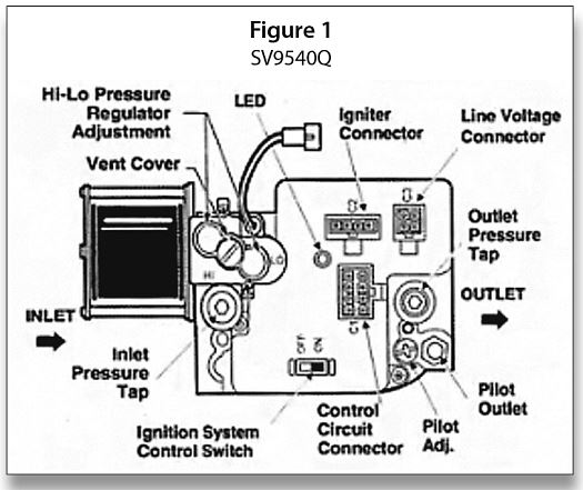
Figure 1 is a top view of the ignition system control. Make note of the black solenoid shown to the left of the main valve body. This is the solenoid, which is directly connected to the gas pressure adjustment for a typical gas valve. This solenoid is powered when high fire is desired and runs on DC voltage, it has a cold resistance of about 130 ohms for troubleshooting purposes to determine if the solenoid is any good.
Manifold Gas Pressure Adjustments (Hi & Lo Fire) (Two Stage Q Model)
In this operation, the gas supply pressure must be within minimum and maximum values listed on rating plate. Gas suppliers usually set pressures. Make adjustment to manifold pressure with burners operating and combustion air box cover removed.
1- Remove combustion air box cover. Set the thermostat 10° above room temperature or use jumpers as mentioned further on.
2- Connect manometer to the tapped opening on the outlet side of gas valve on the manifold pipe. Use a manometer with a 0″–12″ minimum water column range.
3- Turn gas ON. Operate the furnace on high fire by using a jumper wire on the R to W1 and W2 thermostat connections on the fan board.
4- Remove the adjustment screw covers on the gas valve. Turn adjusting screw counterclockwise to decrease the manifold pressure and clockwise to increase.
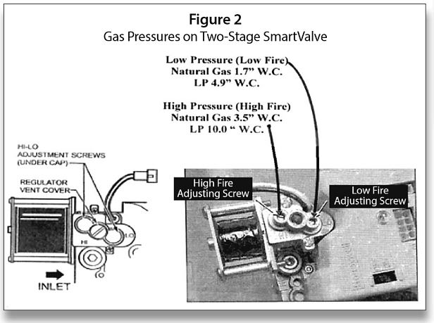
5- Set the manifold pressure to the values shown in Figure 2; in some cases, the high fire for natural gas may be listed at 3.2″ W.C. Follow manufacturer recommendations.
6- Operate the furnace on low fire by using a jumper wire on the R to W1 thermostat connections on the fan board.
7- Repeat steps 4–5 for low fire operation.
8- When the manifold pressures are properly set, replace the adjustment screw covers on the gas valve.
9- Remove the jumper wires from the thermostat connections on the fan board. Remove manometer and replace plug in manifold.
10- Replace combustion air cover.
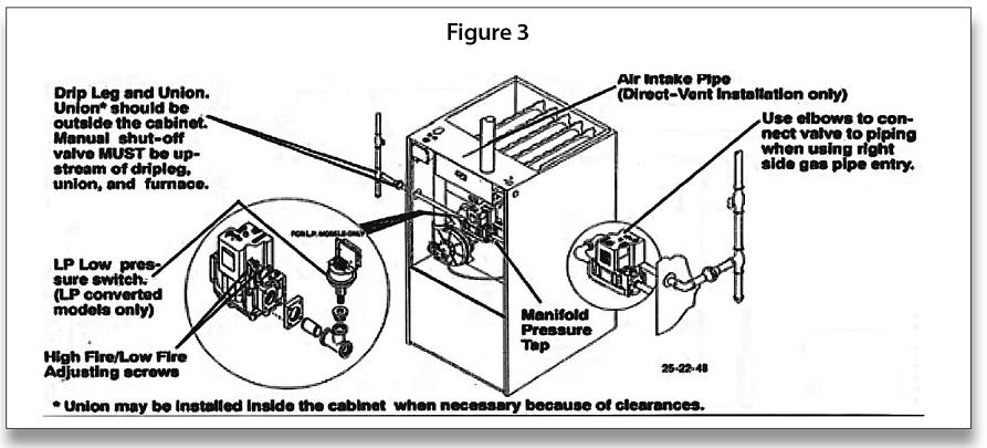
Figure 3 illustrates typical piping arrangements and illustrates the location of pressure adjustments mentioned in Figure 2. It may also be required to have a low-pressure switch installed on LP applications, as shown.
Wiring Diagrams & Circuitry
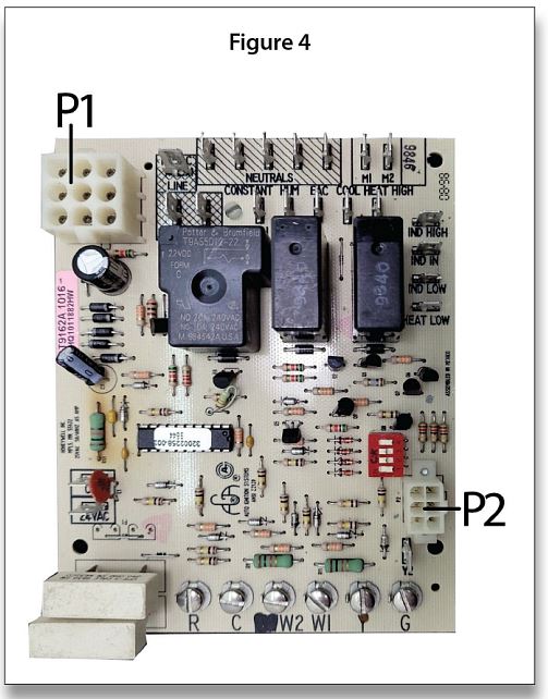
Figure 4 on the following page is a breakdown of the ST9162 board and the locations of the many connectors along with identifing the P1 eight Pin plug in for a wiring harness and the P2 six pin plug in which is connected to the variable speed DC motor.
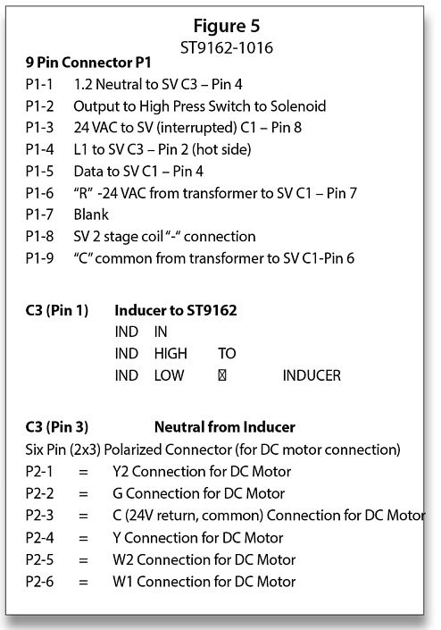
The connections on the ST9162 and SmartValve for connections P1 and P2 along with “C” pin connections for SmartValve are listed above in Figure 5. ICM