Written on: December 29, 2021 by Timmie McElwain
Part III, from the Nov/Dec 2021 Indoor Comfort
Parts I & II, from the Jul/Aug and Sep/Oct 2021 Indoor Comfort can be found here.
As we look into some more modern systems and what specific problems they present, it is important to understand the basic fundamentals associated with these systems. Most of our modern heating equipment in some way or another involves electronics and the use of flame rectification as a safety and flame-proving system.
It doesn’t matter if it is a forced warm air furnace or a forced hot water boiler—the same basic system is used to perform safe ignition followed by consistent operation throughout the entire call for heat.
There are, however, different ways the system is applied from intermittent pilot application to direct spark ignition and including hot surface ignition. Each has its own distinct advantages and problems. We’ll now attempt to resolve those burner problems related to these systems, as well as offer corrections and diagnostics.
We will start with the basics and then continue to operation, typical problems, diagnosis, troubleshooting procedures and a final solution to your particular problem. It’s easy to jump to conclusions with these systems and just change parts to hopefully solve a problem. That is, however, time-consuming and costly.
I invite you to visit our new Facebook page Timmie’s Tips on Gas. I look forward to seeing you there.
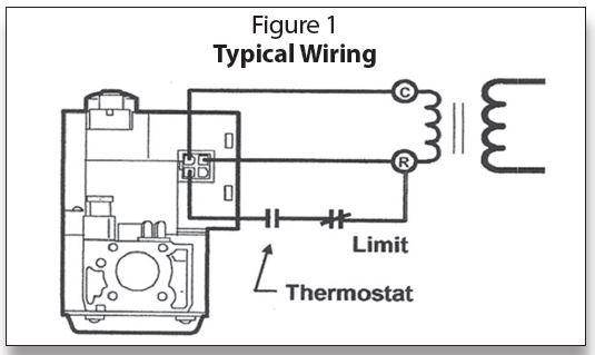
SmartValve™ Typical Wiring
The wiring for the SmartValve™ is fairly simple; it is not much more complicated than wiring for a standing pilot 24-volt system. Figure 1 shows an example of the typical wiring required. It needs a constant, uninterrupted 24 volts to run the electronics in the valve and a 24-volt signal that comes through the thermostat circuit and limits.
A 40 VA transformer, which is National Electrical Manufacturers Association (NEMA) rated Class II Standard DC20-92, is required for the SV9500 series and a 50 VA for the SV9600 Series. The igniter draws about 1.25 amps and the total current required is about 1.5 amps. Figure 2 shows the capacity and versatility of a NEMArated transformer.
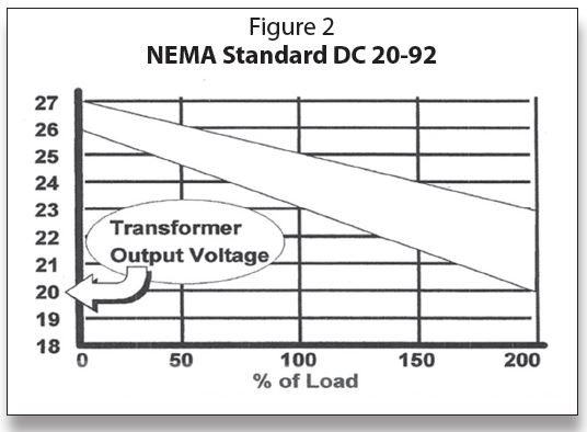
NEMA standards for transformers specify how well the transformer must hold its output voltage under load conditions, as illustrated in Figure 2:
Voltage regulation:
• Nominal rating = 24 volts
• Open circuit = between 26 and 27 (no more than 27 volts)
• Full load = 23 to 25 Volts
• Twice full load = 20 to 23 Volts
SmartValve™ power requirements:
• Valve + igniter + thermostat + fan timer = 1.55 to 1.87 amps
37.2 to 44.9 VA
• Load on 50 VA transformer =
• 40 VA transformer load = 93 to 112%
A lower quality transformer is likely to have the voltage drop off much more rapidly so it will have a higher open circuit voltage. It will also have a lower voltage at 200% of rated load to get to 24 volts at full load.
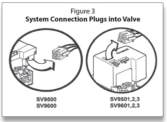
Making connections
One of the changes made from Generation I to II was moving the system connector plug from the side to the top of the control, as illustrated in Figure 3. This plug can be unplugged for service and checkout when necessary; we will expand on troubleshooting in an upcoming column.
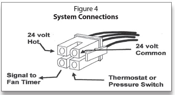
In Figure 4, we have an expanded view of the system connector. Looking at the connector with the clip to the right, the upper left square terminal is 24 volts hot (the “R” terminal from the transformer). To the right is the backwards “D” shaped plug, which is the common terminal (the “C” terminal from the transformer).
The lower right square terminal is the interrupted 24 volts through the thermostat (the anticipator setting is 0.3 amps) and limit controls. The lower left backwards “D” terminal is the EFT (Electronic Fan Timer) output terminal. This is a microprocessor “DATA” signal superimposed on an AC voltage feed to the electronic fan timer to determine the start of the fan on delay timing cycle. It also tells when to start timing the fan-off delay. We will discuss more of this troubleshooting, connector testing and the use of a test harness in a following column.
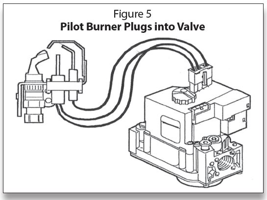
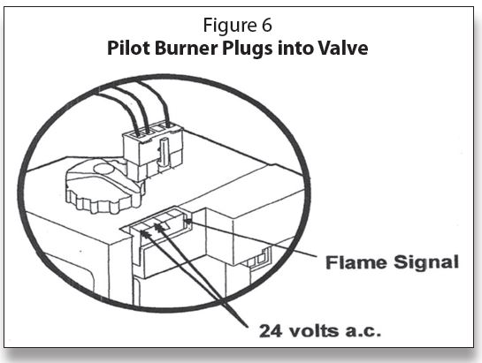
The other plug on top of the SmartValve™ is for the pilot burner, as shown in Figure 5. The pilot connections are 24 volts to the igniter on the two blue wires. The clear wire, or in some cases the black wire, is for the microamp flame signal to get back to the electronics in the valve, as illustrated in Figure 6. This pilot plug-in becomes an excellent point to start troubleshooting on this system; we will discuss more in an upcoming column.
Part numbers
Some miscellaneous information on SmartValve™ Generation I and II concerns natural/liquid propane (LP) conversion and part numbers for orifices and kits for accomplishing conversion. These are shown in Figure 7.
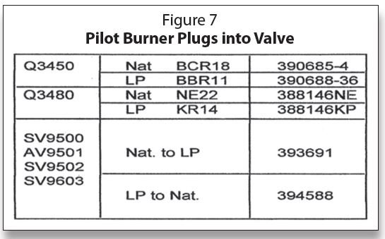
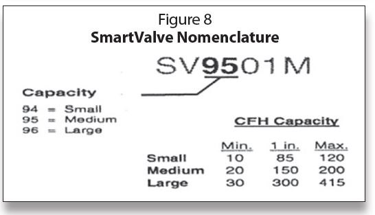
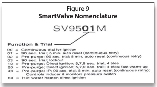
Figure 8 and Figure 9 break down the nomenclature for Generation I and II along with Generation III controls. It also includes the SmartValve™ water heater control numbers.
A list of Universal SmartValve service part replacement numbers that are still being produced, as well as obsolete numbers, can be found in the Tradeline Catalog Cross Reference.
Electronic Fan Timer Output Terminal
Back in Figure 4, we mentioned the “lower left backward D” shaped terminal. This is the Electronic Fan Timer (EFT) output terminal. This is a microprocessor “DATA” signal superimposed on an AC voltage feed to the electronic fan timer to determine the start of the fan on a delayed timing cycle. It also tells when to start timing the fan-off delay. To expand on this, “DATA” is a signal that rides “piggy back” on the AC signal. It carries electronic information to affect the operation of the timer. We will cover troubleshooting SmartValve systems in the next issue of ICM. ICM
Timmie M. McElwain is President of Gas Appliance Service, which provides training for those servicing gas combustion equipment.
He is a certified instructor and test proctor for the Propane Gas Association in their CETP program.