Written on: April 10, 2023 by Timmie McElwain
Parts 1 & 2, from the Jul/Aug and Sep/Oct 2021 Indoor Comfort can be found here.
Part 3, from the Nov/Dec 2021 Indoor Comfort can be found here.
Part 4, from the Jan/Feb 2022 Indoor Comfort can be found here.
Part 5, from the Mar/Apr 2022 Indoor Comfort can be found here.
Part 6, from the May/Jun 2022 Indoor Comfort can be found here.
Part 7, from the Jul/Aug 2022 Indoor Comfort can be found here.
Part 8, from the Sep/Oct 2022 Indoor Comfort can be found here.
Part 9, from the Nov/Dec 2022 Indoor Comfort can be found here.
Part 10, from the Jan/Feb 2023 Indoor Comfort can be found here.
As we look at modern systems and what specific problems they present, it’s important to understand the basic fundamentals associated with these systems.
Most of our modern heating equipment in some way or another involves electronics; along with the use of electronics is the use of flame rectification as a safety and flame-proving system. It doesn’t matter if it is a forced warm air furnace or a forced hot water boiler; the same basic system is used to perform safe ignition, and then consistent operation, throughout the entire call for heat.
There are, however, different ways it is applied, from intermittent pilot application to direct spark ignition and including hot surface ignition. Each system has its own distinct advantages and problems. Next in this series of resolving burner issues related to these systems, we will give you corrections and diagnostics to help solve those problems.
We will start with the basics and go into operation, typical problems, diagnosis, troubleshooting procedures and a final solution to your particular problem. It can be easy to jump to conclusions and change parts until you hopefully solve the problem with these systems. That is, however, time-consuming and costly.
I invite you to visit our new Facebook page, Timmie’s Tips On Gas. I look forward to seeing you there.
We are presently doing a series on Honeywell Smart Valve. Picking up where we left off in the last column, we will continue to cover Smart Valve Generation III, walking you through step-by-step troubleshooting with these controls.
Application
The SV9440, SV9540, and SV9640 SmartValve™
System Controls combine gas flow control and electronic intermittent pilot sequencing functions into a single unit. The Q3450 or Q3480 Pilot hardware supplies the low-voltage igniter, flame sensor and pilot burner much the same as Generation I and II. These ignition system controls provide all gas ignition safety functions by controlling gas flow, ignition source and 120 VAC or 240 VAC combustion air blowers. The controls also monitor the appliance airflow proving switch and limit string to assure proper appliance operation and provide pre-purge, post-purge and timed trial for pilot ignition with 100% shutoff and continuous retry. A diagnostic LED indicates system status.
These controls communicate directly with an electronic fan timer (ST9160 Electronic Fan Timer for single stage applications; ST9162 Electronic Fan Timer for two-stage applications) in typical forced warm air furnace applications. They also interface with the 208907 Terminal Board, providing compatibility with power-stealing thermostats or they directly interface with the appropriate power supplies and a system thermostat for additional appliance applications. When controlled directly by a thermostat, these controls do not provide a post-purge function because power to the control is removed when the thermostat call for heat ends.
The SV9440, SV9540 and SV9640 Systems are suitable for a wide range of fan-assisted combustion gas-fired appliances including furnaces, rooftop furnaces, boilers, unit heaters, infrared heaters, water heaters and commercial cooking appliances. The appliance manufacturer determines the specific application of the SmartValve System.
SmartValve System controls are available in a range of valve capacities. Scan this QR code to see:

Table 1: Valve capacity
Table 2: Gas capacity conversion factors
Table 3: Model number suffix designations (the suffix letter indicates temperature range and regulator type)
This is very similar in operation to Generation I and II using a pilot system. It has the 90-second trial for ignition with the five-minute shutdown before retry. Pre-purge time is 15 seconds; post-purge is 30 seconds (not available when SmartValve System Control is connected directly to the thermostat). Flame failure response time is 1.6 seconds at 2 μA.
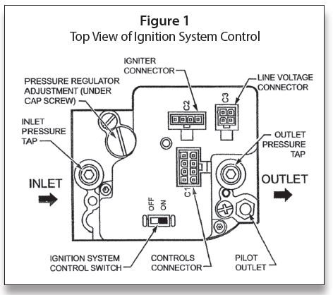
Figure 1 illustrates a top view of the valves; the only difference with this valve is that the igniter output C2 is 24 VAC. There is also 24 VAC interrupter fed to the C1-8 pin that was not used on the SV9510/9520 series SmartValves.
Wiring Diagrams
As we look at Figure 2 with a forced warm air furnace, the wiring is very similar to wiring on the SV9510/9520 series SmartValve. The exceptions are the 24 VAC C2 igniter hook-up on the SmartValve and the use of C1-8 to P1-5 for 24 VAC interrupted 24 volts. The sequence of operation is the same as using the S9160 Electronic Fan Timer as shown in Figure 2.
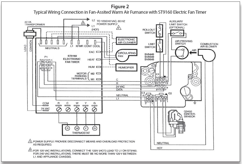
Figure 3 shows SmartValve 9440/9540/9640 used with Honeywell R8285D Boiler Control Center. Once again, this is very similar in operation to the SV9510/9520 Series of SmartValve. The difference is 24 VAC being fed direct from the “R” terminal on the R8285D to C1-8 on the SmartValve. The R/DATA connection is the interrupted 24 volts as the 120 VAC is fed from the junction box direct to C3-2/C3-4. The rest of the sequence is similar to Figure 3.
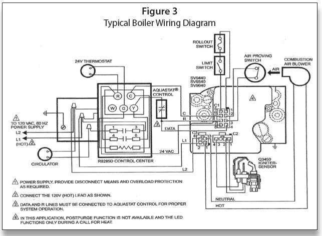
Figure 4 shows a direct connection from the thermostat to SmartValve. This wiring setup could be used with a steam system by wiring the LWCO and Pressuretrol in place of the limit switch. The 120 VAC is fed direct to C3-2/C3-4 from the junction box. The 24 VAC is fed direct from the transformer to C1-8. The R/DATA/W is the interrupted circuit.
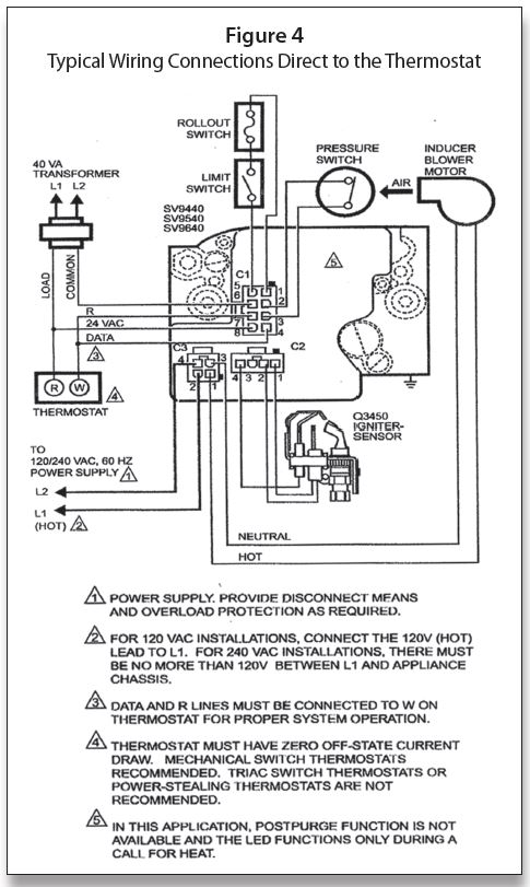
Figure 5 shows the SV9440/9540/9640 with the 208907 terminal board that allows compatibility with power stealing thermostats.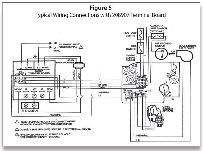
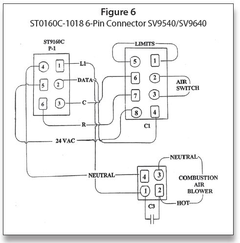
Figure 6 shows the various pin locations and the shape of the pins on both the EFT and the SmartValve.
Scan this QR code to see Figure 7, which is the sequence of operation for the ST9160 EFT or 208907 terminal boards. These boards are used with the SV9541 and SV9641 SmartValve™. When troubleshooting, make note of the igniter turning off after 30 seconds into the 90-second trail for ignition, and remaining off for approximately 25 seconds. It then should come back on for the final 30 seconds of the 90-second trail. The pilot valve is energized during the entire trail for ignition. If the system fails to light after the 90-second trial for ignition, it will go into a five-minute delay and then retry for another 90-second trial. This process will continue until the system finally lights and the main burner is on.

Scan this QR code to read more about troubleshooting with LED indicator assistance for ignition controls using ST9160 fan timer or 208907 terminal board. ICM