Written on: June 1, 2023 by Timmie McElwain
Parts 1 & 2, from the Jul/Aug and Sep/Oct 2021 Indoor Comfort can be found here.
Part 3, from the Nov/Dec 2021 Indoor Comfort can be found here.
Part 4, from the Jan/Feb 2022 Indoor Comfort can be found here.
Part 5, from the Mar/Apr 2022 Indoor Comfort can be found here.
Part 6, from the May/Jun 2022 Indoor Comfort can be found here.
Part 7, from the Jul/Aug 2022 Indoor Comfort can be found here.
Part 8, from the Sep/Oct 2022 Indoor Comfort can be found here.
Part 9, from the Nov/Dec 2022 Indoor Comfort can be found here.
Part 10, from the Jan/Feb 2023 Indoor Comfort can be found here.
Part 11, from the Mar/Apr 2023 Indoor Comfort can be found here.
As we look at modern systems and what specific problems they present, it’s important to understand the basic fundamentals associated with these systems.
Most of our modern heating equipment in some way or another involves electronics; along with the use of electronics is the use of flame rectification as a safety and flame-proving system. It doesn’t matter if it is a forced warm air furnace or a forced hot water boiler; the same basic system is used to perform safe ignition, and then consistent operation, throughout the entire call for heat.
There are, however, different ways it is applied, from intermittent pilot application to direct spark ignition and including hot surface ignition. Each system has its own distinct advantages and problems. Next in this series of resolving burner issues related to these systems, we offer corrections and diagnostics to help solve those problems.
We will start with the basics and go into operation, typical problems, diagnosis, troubleshooting procedures and a final solution to your particular problem. It can be easy to jump to conclusions and change parts until you hopefully solve the problem. That is, however, time-consuming and costly.
I invite you to visit our Facebook page, Timmie’s Tips On Gas, I look forward to seeing you there.
We are presently doing a series on Honeywell Smart Valve. Picking up where we left off in the last column, we will continue to cover Smart Valve Generation III, walking you through step-by-step troubleshooting with these controls. This article will need to be in perhaps two or three parts in order to illustrate the characteristics of this two-stage system and make them understood.
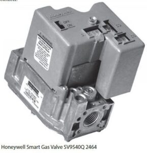
SV9540Q/ST9162 SmartValve Two Stage Heating
The system featured is the SmartValve™ using the SV9540Q two stage gas valve, used on Comfortmaker® furnace models NTVM/VNK. This series furnace is from International Comfort Products Corp. of Lewisburg, TN, and is now perhaps an older system but is still applicable for your education on these systems.
This instruction is not designed to be an installation or service manual for this furnace; rather, the purpose is to show the operation of a two-stage system. The troubleshooting of this system is also included and the features of this furnace will be presented to help provide an understanding of the two-stage system.
Unlike single-stage furnaces that deliver heat unevenly, this variable speed, two-stage gas furnace provides consistent heat and overall comfort. The difference is that the two-stage system produces heat for normal temperatures most of the time, automatically ramping up to higher heat production as needed. Unlike the single-stage, which heats fast and shuts down fast because it’s set for the coldest extremes, this system keeps the home warm without those annoying hot and cold spots.
The furnace is remarkably quiet, thanks to its variable speed circulation blower. It runs quietly in the slower speed, and gently—quietly—increases to the higher speed, as more heat is needed. You can even run the variable speed blower continuously at the lower speed to improve air quality around the clock. Pre-wiring also allows for addition of electronic air filters and humidification.
This 90+ system takes fuel efficiency to its highest level. The variable speed blower also adds an efficiency boost, cutting electrical costs up to 75% compared to standard blowers. This ECM DC voltage motor operates at 500 watts, at ½ speed 90 watts (economy).
Furnace Basics
The thermostat calls for heat and the gas valve is energized by the control system. The burners ignite and the induced draft fan draws the flame into and through the sealed primary heat exchanger. Then, the hot flue gases are pulled from the primary heat exchanger into the secondary heat exchanger, increasing efficiency. The variable speed blower moves another stream of air over the outside of both heat exchangers and brings the warm air into the home. The combustion products are safely vented outside.
This furnace features:
• Two-stage redundant gas valve
• Two-speed induced combustion fan
• Variable speed circulation blower motor
The Honeywell SV9541Q is a two-stage valve, which combines gas flow control and electronic intermittent pilot sequencing functions into a single unit. The Q3450 or 03480 Pilot hardware supplies the low voltage igniter, flame sensor and pilot burner. These ignition system controls provide all gas ignition safety functions by controlling gas flow, ignition source, and a 120 VAC or 240 VAC combustion air blower. The controls also monitor the appliance airflow proving switch and limit string to assure proper appliance operation, and provide pre-purge, post-purge and timed trial for pilot ignition with 100% shutoff and continuous retry. A diagnostic LED indicates system status.
Sequence of Operation
This system is unique as a two-stage system in that it starts on high fire and then, if there is no actual high fire call, it will go to low fire. This allows the development of some Delta “T” to develop in the plenum and duct system (as this is a condensing furnace, it also allows some development of flue gas vaporization). Figure 1 illustrates the sequence as outlined step-by-step below with a bar graph.
(A more specific application to the ComfortMaker Furnace will be illustrated in the next issue).
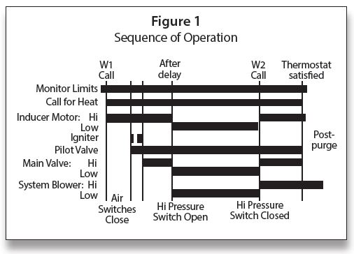
The sequence of operation is as follows:
• Thermostat call—W1
• Combustion air blower—high speed
• Air proving switches
• Pilot flame lit and proved
• Main burner—high fire
• After delay—low speed combustion blower and low fire
• Fan timer
• Circulating fan—low speed
• Thermostat call—W1/W2
• Combustion air blower—high speed
• Air proving switches
• Main burner—high fire
• Circulating fan—high speed
Controls & Accessories
Thermostat
The two-stage furnace control will operate with a two stage-heating thermostat and will provide two-stage heating operation. For two-stage thermostat installations, the R, W1 and W2 wires from the thermostat connect to the R, W1 and W2 connections on the furnace control as shown in Figure 2. During operation, the furnace will shift from low fire to high fire as requested by the thermostat. The thermostat heat anticipators should be adjusted to a .10 setting.
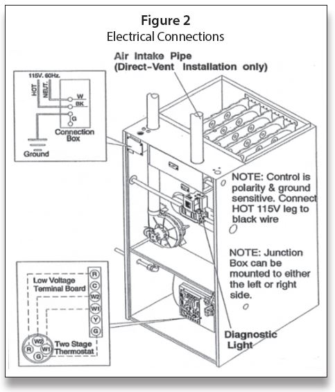
Line voltage connection is also shown in Figure 2; it is important to follow correct polarity, as electronic controls may not function correctly with reverse polarity.
Low voltage connections to furnace must be made on terminal board to fan control.
Optional Equipment
All wiring from furnace to optional equipment must conform to local codes or, in the absence of local codes, the applicable national codes. Install wiring in accordance with manufacturer’s instructions.
Humidifier/Electronic Air Cleaner
The furnace is wired for 120 VAC humidifier and/or electronic air cleaner connection.
The fan control is wired for 24 VAC normally open (N/O) dehumidistat connection. Connect dehumidistat to the Y terminal and the ¼” male quick connect Y2 terminal on the fan control (scan the QR code at left to see the complete Furnace Wiring Diagram). A 20% reduction of cooling airflow will occur when the Y2 dehumidistat terminal is energized during a call for cooling from the thermostat.
Fan Control
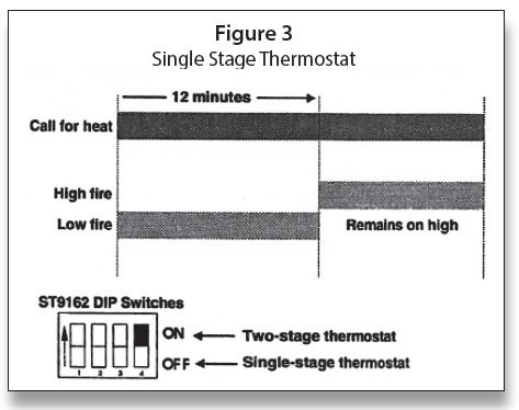
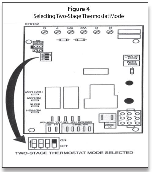
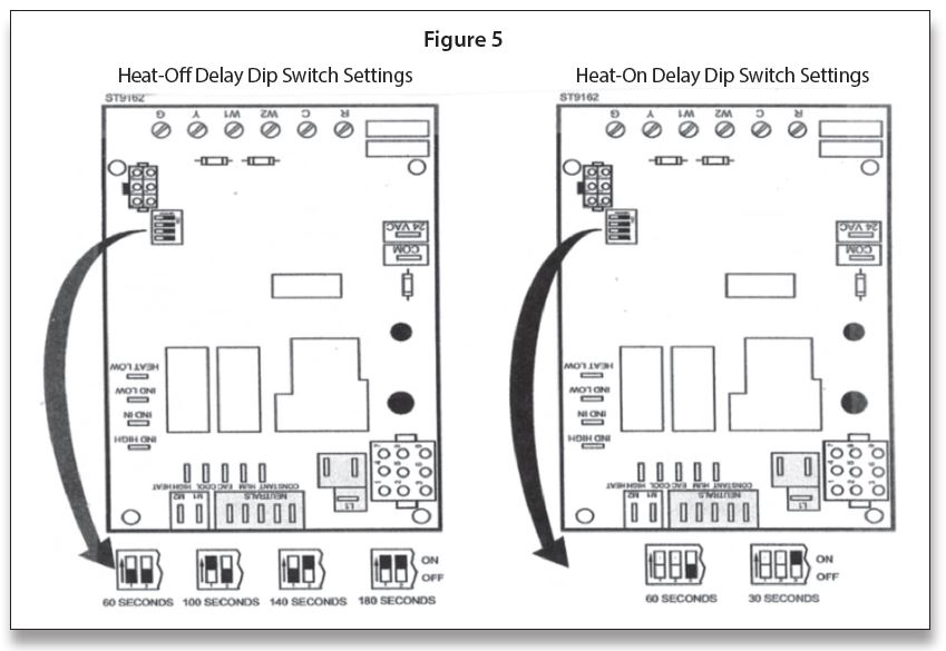
The fan control is preset at the factory with an adjustable blower On delay of 30 seconds in the heating mode. The blower Off timing is preset at 140 seconds. If desired, the fan On delay and Off delay can be reset (See Figure 3 and Figure 4 for location of dip switches) to obtain the longest delay times while still maintaining comfort levels (scan QR code at left for Furnace Wiring Diagram).
NOTE: To achieve maximum efficiency, it is recommended that the fan control be set to turn on at 30 seconds after the burners light.
The ST9162 can be used as a two-stage or single-stage. When the choice is made, the dip switches on the EFT must be set as shown in Figure 3.
The dip switch settings for Heat-On and Heat-Off delay are shown in Figure 5.
In the next issue, we will pick up with SmartValve Two Stage with Comfortmaker Sequence of Operation. ICM