Written on: February 14, 2022 by Timmie McElwain
Part IV, from the Jan/Feb 2022 Indoor Comfort
Parts I & II, from the Jul/Aug and Sep/Oct 2021 Indoor Comfort can be found here.
Part III, from the Nov/Dec 2021 Indoor Comfort can be found here.
As we look into some more modern systems and what specific problems they present, it is important to understand the basic fundamentals associated with these systems. Most of our modern heating equipment in some way or another involves electronics and the use of flame rectification as a safety and flame-proving system.
It doesn’t matter if it is a forced warm air furnace or a forced hot water boiler—the same basic system is used to perform safe ignition followed by consistent operation throughout the entire call for heat.
There are, however, different ways the system is applied from intermittent pilot application to direct spark ignition and including hot surface ignition. Each has its own distinct advantages and problems. We’ll now attempt to resolve those burner problems related to these systems, as well as offer corrections and diagnostics.
We will start with the basics and then continue to operation, typical problems, diagnosis, troubleshooting procedures and a final solution to a particular problem. It’s easy to jump to conclusions with these systems and just change parts to hopefully solve a problem. That is, however, time-consuming and costly.
I invite you to visit our new Facebook page I look forward to seeing you there.
SmartValve™ Generation I & II Troubleshooting
The troubleshooting of the SmartValve™ itself is fairly simple. We will, however, incorporate the valve into some actual systems. We will address a forced warm air system first. The low voltage portion of a warm air system is shown in Figure 1 with an EFT (Electronic Fan Timer). The line voltage portion of the system is shown in Figure 2.
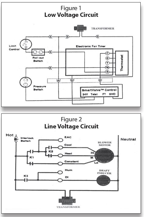
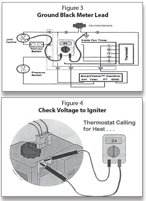
Figure 3 illustrates a method of using a multimeter. That is grounding one lead of the meter to the common side of the transformer, the “C” terminal, and leaving it there. The other lead is used to go from control to control to check for voltage.
The best place to start troubleshooting is at the output to the igniter shown in Figure 4. With the thermostat calling or not with power applied, you should have 24 volts at that location. If there are 24 volts there you know the transformer is good, the 120 volts are good. If you have problems, then it is probably in the igniter sensor. One more important time-saver is—when troubleshooting with a combustion air blower on the equipment—if the blower runs, the 24 volts and 120 volts are okay. Obviously if there is a problem with 120 or 24, the combustion air blower would not run. If you have 24 volts at the output terminals and the system does not light, then the problem is with the igniter itself.
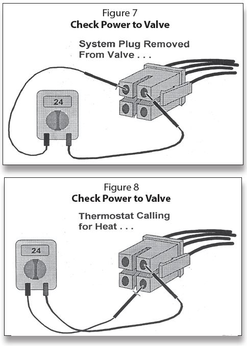
At the same time, with the igniter sensor disconnected, switch your meter over to the ohms scale and check the igniter resistance by going across the two terminals connected to the blue wires as illustrated in Figure 5. A new igniter is usually 2–4 ohms resistance. Up to 10 ohms is okay; anything over 10-ohm will require igniter replacement.
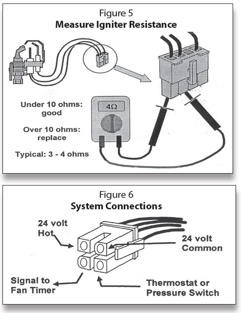
If you do not have 24 volts at the output to the igniter, then check power to the valve at the control plug as shown in Figure 6:
Electrical connections:
• 24 volt common goes to the grounded side of the transformer secondary—“C” on the transformer.
• 24 volt hot goes to the hot side of the transformer secondary—“R” on the transformer.
• Thermostat terminal brings the call for heat signal from the thermostat or pressure switch, depending on the type of equipment and control circuit.
• The thermostat does not carry the igniter current.
• Anticipator setting is .3 amps safely within the adjustment range of all electromechanical thermostats.
The Electronic Fan Timer (EFT) signal is on whenever the main valve is open and:
• Tells when to start timing the Fan-On delay.
• Tells when to start timing the Fan-Off delay.
In checking the control plug, as shown in Figure 7, you should have 24 volts at all times when the power is on. This is the uninterrupted voltage. If 24 volts are not measured here, check the transformer. If you have 24 volts here, check the two right-hand terminals as shown in Figure 8. If there are not 24 volts on the terminals, one of the controls is open in either the thermostat, limits or even the pressure switch.
It is also a good idea to make sure that there is no appreciable loss of voltage in the conditions of under load (thermostat calling) shown in Figure 9 and no load (no call for heat) shown in Figure 10. Whether load or no load, voltage should remain between 19 to 28 volts.
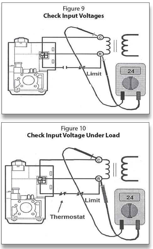
The SmartValve™ system needs an uninterrupted 24 volts to run the electronics in the valve and then a 24-volt signal through the thermostat circuit on a call for heat. By using the correct size transformer, a stable voltage should be able to be maintained. When the SmartValve™ has energized the igniter, check the voltage; if the voltage holds up under that load, it should remain a stable 24 volts. The more it deviates from the 24 volts, the more the problem is likely to be the transformer, or perhaps the line voltage to the transformer. It could also be an indication that the valve is increasing appreciably in resistance, thereby demanding greater current flow and causing the voltage to decrease.
Microamps
The ability to prove the flame and safely light the main burner is accomplished by the process of flame rectification. The Generation I electronic systems produce a 24-volt superimposed voltage from within the valve electronics. This signal is passed through the flame and produces a DC microamp signal of 0.3μ amp minimum. This voltage determines the intensity of the microamp signal. If the system is not working correctly, this check will be the first step in proving if the problem is microamps or the valve itself. For readings:
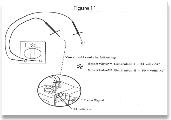
• The Generation I signal is 24 volts
• The Generation II signal is 80+ volts
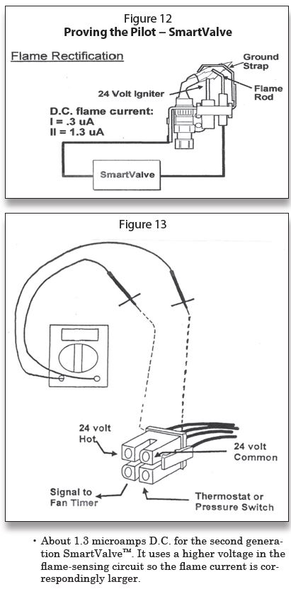
See the Generation I and II signals in Figure 12. These voltages can be checked. With the igniter plugged into the gas valve (the illustration in Figure 11 shows it unplugged; it should be plugged in), ground one lead of the multimeter to ground (the gas valve is a good ground) while the other lead is inserted at the back side of the pilot harness on the black or clear wire microamp wire. Note: a paper clip fits nicely into the back of the harness for this reading.
If the readings are less than required, then replace the SmartValve™. Note: microamp readings cannot be obtained unless you have a special test harness, which is discussed later in this article. The minimum microamps for each generation is shown in Figure 12.
Flame proving circuit:
• About 0.3 microamps D.C. for the first generation SmartValve™. It uses 24 volts in the flame-sensing circuit and so the flame current is relatively small.
In addition to voltage checks, another indicator is the status of the igniter. This can be in the place of microamp readings
• If the igniter is off and the pilot is lit, but the main valve will not open, then the problem is not in the sensing circuit (Microamps) but in the main valve. If the igniter is off, you know the flame has been detected.
• If the pilot is lit and the igniter is still glowing, but the main valve will not open, then the problem is in the sensing circuit.
On Warm Air Systems, there will be an output signal available from the SmartValve™ to trigger the Electronic Fan Timer (EFT). It is the fourth terminal located on the lower left-hand side—a backwards “D” shape.
The signal is on whenever the main valve is open and is a DATA signal to the microprocessor on the circuit board. It:
• Tells when to start timing the Fan-On delay
• Tells when to start timing the Fan-Off delay
The output from this terminal on the connector can be measured and should be between 15 to 28 volts AC. This can be measured by placing a paper clip, attached to the alligator clip on the meter lead, and inserting it into the back of the control plug as shown in Figure 13 (the plug is shown detached; it should actually be plugged into the valve). It should be placed between Common and the EFT output terminal. You could also obtain this reading by using the Input Voltage Test Harness.
There is a SmartValve™ Input Voltage Test Harness available for troubleshooting these systems. It is Honeywell Part No. 396085. There is also a kit to measure Microamps. It is Measuring SmartValve™ System Flame Current, Part No. 395466.
We will discuss troubleshooting the Smart-Valve™ in an upcoming issue. ICM
Timmie M. McElwain is President of Gas Appliance Service, which provides training for those servicing gas combustion equipment. He is a certified instructor and test proctor for the Propane Gas Association in their CETP program.