Written on: April 18, 2022 by Timmie McElwain
Part V, from the Mar/Apr 2022 Indoor Comfort
Parts I & II, from the Jul/Aug and Sep/Oct 2021 Indoor Comfort can be found here.
Part III, from the Nov/Dec 2021 Indoor Comfort can be found here.
Part IV, from the Jan/Feb 2022 Indoor Comfort can be found here.
As we look into some more modern systems and what specific problems they present, it is important to understand the basic fundamentals associated with these systems. Most of our modern heating equipment in some way or another involves electronics and the use of flame rectification as a safety and flame-proving system.
It doesn’t matter if it is a forced warm air furnace or a forced hot water boiler—the same basic system is used to perform safe ignition followed by consistent operation throughout the entire call for heat.
There are, however, different ways the system is applied from intermittent pilot application to direct spark ignition and including hot surface ignition. Each has its own distinct advantages and problems. We’ll now attempt to resolve those burner problems related to these systems, as well as offer corrections and diagnostics.
We will start with the basics and then continue to operation, typical problems, diagnosis, troubleshooting procedures and a final solution to a particular problem. It’s easy to jump to conclusions with these systems and just change parts to hopefully solve a problem. That is, however, time-consuming and costly.
I invite you to visit our new Facebook page Timmie’s Tips on Gas. I look forward to seeing you there.
This article covers some of the tools and aids available to troubleshoot SmartValve™ Generation I and II. Most of these aids can be purchased at your local heating supply stores with the part numbers mentioned here.
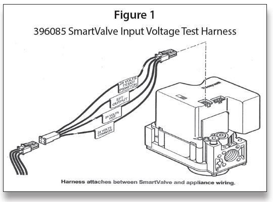
SmartValve™ Input Voltage Test Harness (Part # 396085)
The 396085 SmartValve™ Input Voltage Test Harness shown in Figure 1 helps a user to confirm proper appliance control string operation in the field. When installed between the appliance harness and the SmartValve™, the 396085 Test Harness is used to connect a voltmeter to the SmartValve™. This allows the user to monitor the input signals to the SmartValve™ controls. Proper SmartValve™ operation requires the appliance control string to supply the needed input signals during a call for heat.
Test Procedure
Note: Leave SmartValve™ switch in ON position.
1. Turn off gas supply at the appliance shut-off valve.
2. Make sure appliance is powered.
3. Lower the temperature controller setting to make sure there is no call for heat.
4. Disconnect the appliance wiring harness (2×2 connector) from the SmartValve™.
5. Connect the test harness between the appliance wiring and the SmartValve™, as shown in Figure 1. Make sure the keyed connectors lock into place.
6. Measure the voltage between the 24-volt hot (white label) lead and the 24-volt common (gray label) lead on the test harness. If the voltage is less than 20 volts or more than 28 volts, check the appliance power supply and the system transformer for proper functioning. Note: If an appliance is wired so the 24-volt hot lead is controlled with the 24-volt TSTAT/ PSWITCH (yellow label) lead, there is no voltage between the 24-volt hot lead and the 24-volt common lead in Step 6.
7. Disconnect the voltmeter or multimeter from the 24-volt hot lead.
8. Connect the voltmeter or multimeter to the 24-volt TSTAT/PSWITCH (yellow label) lead.
9. Set the temperature controller so it calls for heat.
10. Make sure the meter displays nominal 24 volts while the light-off sequence progresses, and the reading is steady with the element glowing. Note: Thevoltage in Steps 10 and 11 should be between 19 VAC and 26 VAC with the Q3450 element glowing and the gas turned off. If the measured voltage is outside the acceptable range, analyze the appliance control string, input voltage supply and the transformer to identify the problem. Correct the problem and retest the appliance.
11. If the voltage is within the acceptable range, turn off the call for heat and make sure the measured voltage decreases to zero.
12. Disconnect the voltmeter or multimeter leads from the test harness.
13. Connect the leads to the EFT output (green label) lead and the 24-volt common lead.
14. Turn on the gas supply.
15. Initiate a new call for heat.
16. When the appliance main burner lights, measure the voltage between the EFT output lead and the 24-volt common lead. This is a logic signal and can range from 15 VAC through 28 VAC.
17. Test is complete. Turn off appliance call for heat.
18. Disconnect the test harness from the SmartValve™.
19. Connect the appliance wiring harness to the SmartValve™.
20. Turn on call for heat and make sure the appliance works properly.
Measuring SmartValve™ System Flame Current (Part # 395466)
This Honeywell SmartValve™ System flame current kitallows the trained service technician to determine flame current levels generated in a SmartValve™ System equipped gas-fired appliance. Knowing the strength and stability of the flame current signal being generated by the appliance can help the technician diagnose intermittent appliance operation and predict future appliance problems.
Many factors influence the flame current being generated by an installed appliance. The ignition control generates an AC voltage potential between the flame sense rod and the burner ground area. When flame is present, the geometry of the flame rod/ground area (1–4) combines with the voltage potential present to generate a low-level (microamperes) rectified DC current. The ignition control monitors this current to determine if sufficient flame is present to operate the appliance. If the appliance does not generate sufficient flame current, the main burner will not operate and the appliance will not deliver heat. If the flame current generated is unstable and fluctuates, there is high likelihood for inconsistent appliance operation. The service technician must insure that the appliance generates a strong and steady flame current well above the minimum threshold to assure reliable appliance operation.
Honeywell SmartValve™ Systems are available with two types of ignition sequences:
• Intermittent pilot models use a low voltage hot surface ignition (HSI) element to light the pilot gas; main burner gas flows and the main burner lights when the pilot flame is sensed.
• Direct hot surface ignition models use a 120-volt hot surface ignition element to directly light main burner gas; if the main flame is sensed at the end of the trial for ignition, the main burner continues to fire.
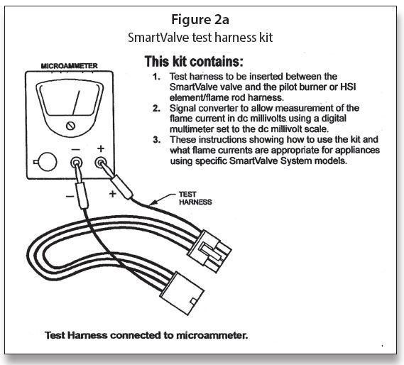
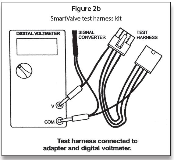
The kit shown in Figure 2a and Figure 2b is suitable to measure flame current on both types of systems. Select the proper procedure, below, based on the type of SmartValve™ System in the appliance. Equipment needed:
1. Analog DC microammeter, such as Honeywell W136, which has a 0 to 25 microampere range, or
2. Digital volt-ohmmeter with a DC millivolt scale
Measuring Pilot Burner Flame Current On Intermittent Pilot SmartValve™ Systems
Intermittent Pilot SmartValve™ Systems include: SV9401, SV9402, SV9403, SV9501, SV9502, SV9503, SV9601, SV9602, SV9440, SV9450, SV9541 and SV9640.
When testing with this kit in Figures 2a and 2b:
1. Read these instructions carefully. Failure to follow the instructions can damage the product or cause hazardous conditions.
2. Check the ratings given in the instructions and on the product to make sure the product is suitable for your application.
3. Troubleshooter must be a trained, experienced service technician.
4. After completing the measurements, use the appliance instructions to check the product operation.
 IMPORTANT: Accurate flame current measurement can be performed only with the pilot flame lit and the main flame not lit. When measuring with this kit, the appliance main burner orifices should be temporarily plugged while measuring system flame current. Be sure to remove the temporary plug and check the appliance for proper operation after completing the test.
Direct Measurement
Note: Direct measurement requires an analog DC micro-ammeter capable of reading to 0.01-microampere accuracy. No signal converter required.
1. Disconnect all power to the appliance.
2. Connect the test harness between the valve control and the pilot burner.
a. Insert the banana plug connected to the valve side of the test harness into the positive (+) jack on the DC microammeter as shown in Figure 2a.
b. Insert the other banana plug connected to the pilot burner side of the test harness into the negative (-) jack on the DC micro-ammeter as shown in
Figure 2a.
3. Reconnect power to the appliance.
4. Generate a call for heat.
5. Make sure the pilot flame lights and the main burner does not light.
6. After the pilot flame is on for ten seconds, read the DC micro-ammeter. The readings must be steady.
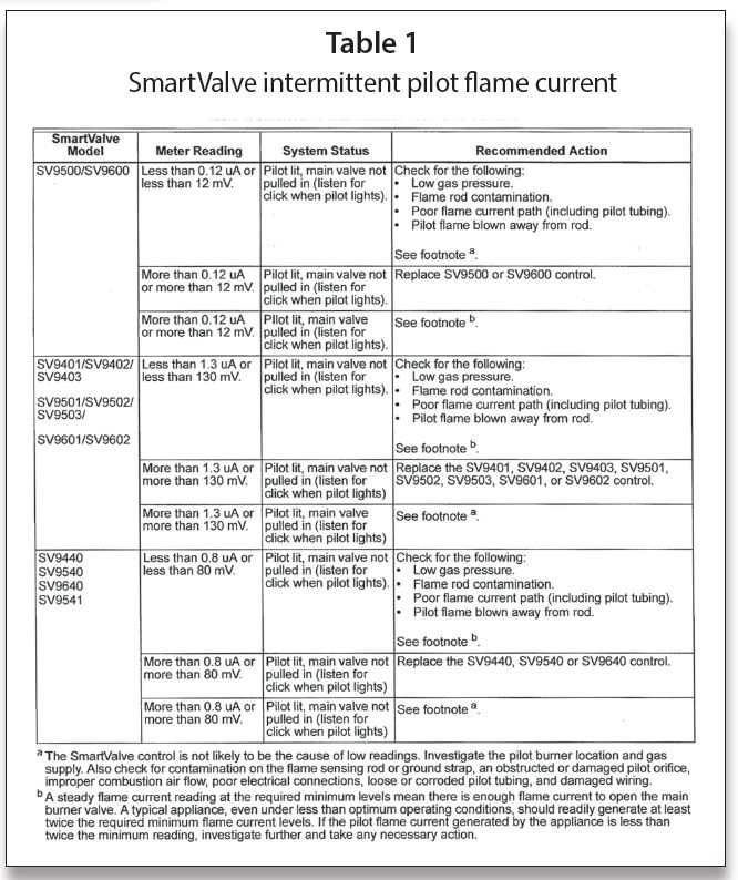
7. Take the action recommended in Table 1.
Millivolt Measurement
Note: Millivolt measurement requires a digital voltmeter capable of reading DC millivolts. Use the signal converter included with this kit. See Figure 2b.
1. Disconnect all power to the appliance.
2. Connect the signal converter to the voltmeter.
3. Set the voltmeter to read DC millivolts.
Note: The signal converter is not polarity sensitive.
4. Connect the test harness between the valve control and the pilot burner.
a. Insert the valve side of the test harness through the female end of the signal converter connector and into the positive (+) jack of the digital voltmeter, as shown in Figure 2b.
b. Insert the pilot burner side of the test harness through the female end of the signal converter connector and into the negative (-) jack of the digital voltmeter, as also shown in Figure 2b.
5. Reconnect power to the appliance.
6. Generate a call for heat.
7. Make sure the pilot flame lights and the main burner does not light.
8. After the pilot flame is on for 10 seconds, read the digital voltmeter. The readings must be steady.
9. Take the action recommended in Table 1.
The SmartValve™ Input Voltage Test Harness available for troubleshooting these systems is Honeywell Part # 396085. The Measuring SmartValve™ System Flame Current (Part # 395466) is the kit to measure Microamps.
There will be more on troubleshooting SmartValve™ in the next article.
Finally, I love to teach and would love to have you join us for some training. We conduct seminars on the following topics and many others:
One-Day Course:
• Powerpile Systems
Three-Day Course:
• Combustion Testing Design Gas Equipment
• Conversion Burners
Four-Day Course Designed for Your Specific Need:
• Modulating/Condensing Boilers
Five-Day Course:
• Fundamentals of Gas
• Circuitry and Troubleshooting
• Hydronic Controls
• Electric Ignition Systems
• Advanced Electric Ignition Systems
For more information, Tel: 401-437-0557; E-mail: timmcelwain@gastcri.com or write to: Gas Appliance Service Training & Consulting, 42 Village Dr., Riverside, RI 02915. ICM