Written on: February 13, 2023 by Timmie McElwain
Parts 1 & 2, from the Jul/Aug and Sep/Oct 2021 Indoor Comfort can be found here.
Part 3, from the Nov/Dec 2021 Indoor Comfort can be found here.
Part 4, from the Jan/Feb 2022 Indoor Comfort can be found here.
Part 5, from the Mar/Apr 2022 Indoor Comfort can be found here.
Part 6, from the May/Jun 2022 Indoor Comfort can be found here.
Part 7, from the Jul/Aug 2022 Indoor Comfort can be found here.
Part 8, from the Sep/Oct 2022 Indoor Comfort can be found here.
Part 9, from the Nov/Dec 2022 Indoor Comfort can be found here.
As we look into some more modern systems and what specific problems they present, it is important to understand the basic fundamentals associated with these systems. Most of our modern heating equipment in some way or another involves electronics and the use of flame rectification as a safety and flame-proving system.
It doesn’t matter if it is a forced warm air furnace or a forced hot water boiler—the same basic system is used to perform safe ignition followed by consistent operation throughout the entire call for heat.
There are, however, different ways the system is applied from intermittent pilot application to direct spark ignition and including hot surface ignition (HSI). Each has its own distinct advantages and problems. We’ll now attempt to resolve those burner problems related to these systems, as well as offer corrections and diagnostics.
We will start with the basics and then continue to operation, typical problems, diagnosis, troubleshooting procedures and a final solution to a particular problem. It’s easy to jump to conclusions with these systems and just change parts to hopefully solve a problem. That is, however, time-consuming and costly.
I invite you to visit our new Facebook page Timmie’s Tips on Gas. I look forward to seeing you there.
We are presently doing a series on Honeywell SmartValve; in this article we will cover SmartValve Third Generation and walk you through the step-by-step process of operation with these controls.
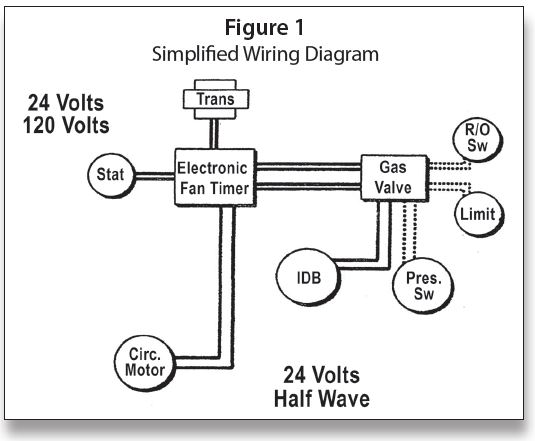
Something new has been added to be able to distinguish between controls and their functions. They are using different voltages and rectifications to carry DATA signals. This helps to define the difference electronically between limits and other controls in the system. This is illustrated in Figure 1: Simplified Wiring Diagram.
This is nothing to get concerned about, as a switch is either “open” or “closed” and the voltage readings are always this—across an open switch you will read “voltage” and across a closed switch you will read “zero.” To troubleshoot, as always, you can jump out switches.
Here are a few new things to keep in mind while troubleshooting:
• Air proving switch and limit string use 24 volt half wave rectified current
• Volt meter checks will give different readings
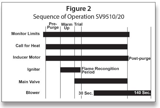
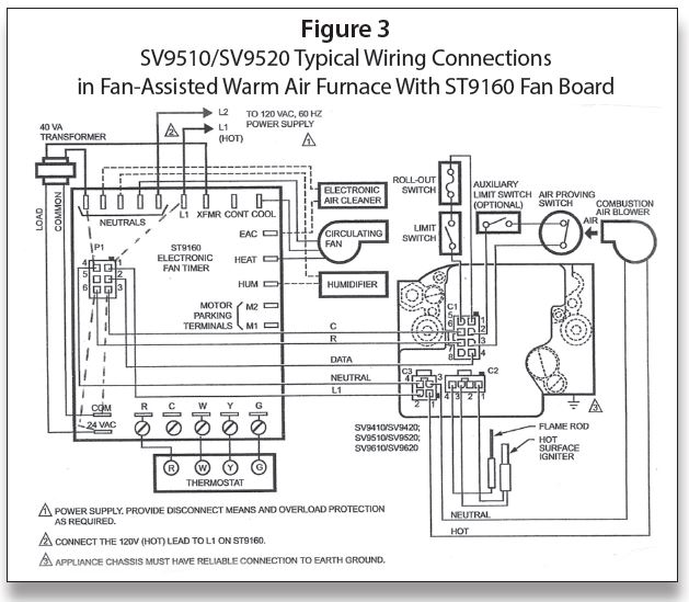
Figures 2 and 3 are from the November/December column. They are necessary in order to trace through the diagram.
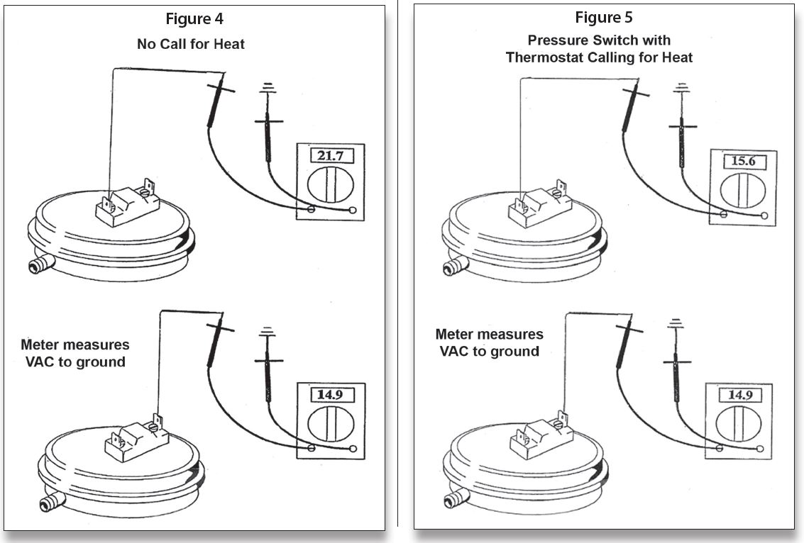
With no call for heat in Figure 4, the voltages shown were recorded. To be able to see the effect of operation on the pressure switch as to voltage readings, I simulated blocked pressure switch tubing in Figure 5; all that changed was the readings—in both cases it was an open pressure switch.
Be careful to wait for the prepurge and igniter warm up time when diagnosing problems. Depending on those times, it can be up to a minute before you will have burner ignition. These systems also have a very short trial for ignition. Be aware of the sequence of operation and watch for any deviations from the normal operation.
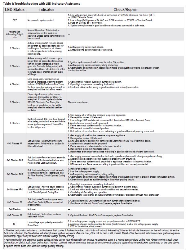
For a trouble diagnosis, refer to the specific LED code as outlined in Table 1: Troubleshooting with LED Indicator Assistance. Newer versions have the expanded 6 code diagnostics with the 10 flash indicating reverse polarity.
In addition to the codes and other diagnostics available, checks can be done with a multimeter. Using the diagram in Figure 3, the following checks should be made for Direct Spark Ignition (DSI) igniter troubleshooting:
• Wait for pre-purge and igniter warm-up
• Short trial for ignition
• Watch for any deviation from sequence of operation
Here are more in-depth directions for troubleshooting:
1. L1 to Neutral should have 120 VAC; L1 to ground should read 120 VAC; if not then polarity may be reversed.
2. XFMR (transformer) to Neutral should have 120 VAC.
3. COM – 24 VAC should have 24 volts AC.
4. With a call for heat from the thermostat or by jumping “R” to “W,” you should have 120 VAC at C3-1/C3-2 and the Combustion Air Blower should be running.
5. Accounting for the time for prepurge, you should have 120 VAC at C2-1/C2-3 and the igniter should be glowing and the Air Proving Switch should be closed.
6. Accounting for igniter warm-up time, there should be 24VAC at C1-7/C1-6 and the Smart Valve should be energized. If not, check the limit switch, roll out switch or air proving switch string for an open switch.
7. When the burner is up and running, you should have a DATA signal coming out of C1-4 and going into P1-2 on the EFT. After the fan delay time is satisfied, the Circulating Fan should be on—if not, check for 120 VAC from the HEAT terminal on the EFT; it should be set to Neutral. If you have power to the fan and it is not running, replace the fan.
Also keep in mind:
• Use troubleshooting table in spec sheet and LED
• Using both should lead you to the trouble
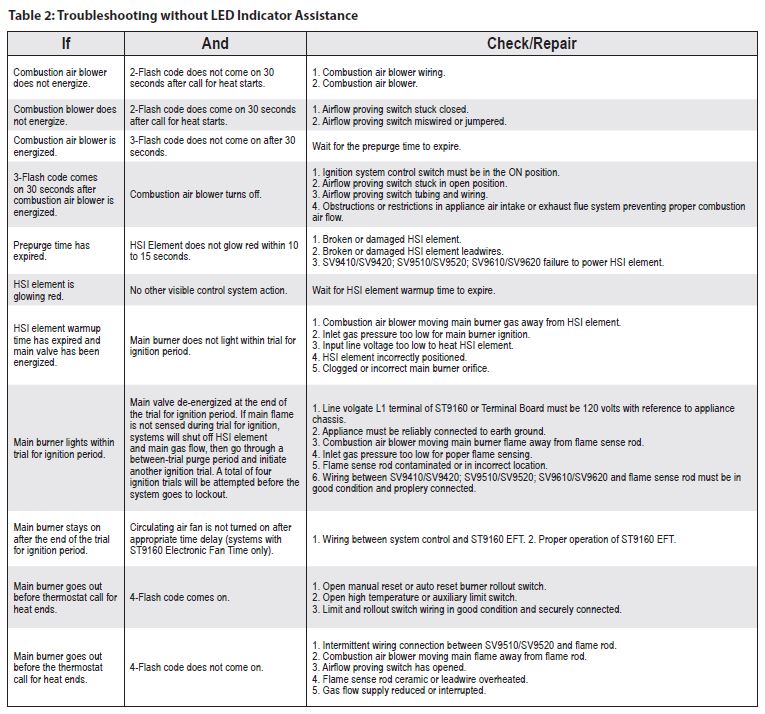
These LED codes are for the older version Smart-Valve, the newer ones have the extended code as shown in Table 1. There is also a procedure for troubleshooting without the codes just in case they are not working or the power was shut off before the technician arrived to fix the problem. It is illustrated in Table 2. ICM