Written on: August 15, 2022 by Timmie McElwain
Part 7, from the Jul/Aug 2022 Indoor Comfort
Parts 1 & 2, from the Jul/Aug and Sep/Oct 2021 Indoor Comfort can be found here.
Part 3, from the Nov/Dec 2021 Indoor Comfort can be found here.
Part 4, from the Jan/Feb 2022 Indoor Comfort can be found here.
Part 5, from the Mar/Apr 2022 Indoor Comfort can be found here.
Part 6, from the May/Jun 2022 Indoor Comfort can be found here.
As we look into some more modern systems and what specific problems they present, it is important to understand the basic fundamentals associated with these systems. Most of our modern heating equipment in some way or another involves electronics and the use of flame rectification as a safety and flame-proving system.
It doesn’t matter if it is a forced warm air furnace or a forced hot water boiler—the same basic system is used to perform safe ignition followed by consistent operation throughout the entire call for heat.
There are, however, different ways the system is applied from intermittent pilot application to direct spark ignition and including hot surface ignition. Each has its own distinct advantages and problems. We’ll now attempt to resolve those burner problems related to these systems, as well as offer corrections and diagnostics.
We will start with the basics and then continue to operation, typical problems, diagnosis, troubleshooting procedures and a final solution to a particular problem. It’s easy to jump to conclusions with these systems and just change parts to hopefully solve a problem. That is, however, time-consuming and costly.
I invite you to visit our new Facebook page Timmie’s Tips on Gas. I look forward to seeing you there.
Forced hot water boiler wiring diagram
I want to emphasize once again how important knowing the sequence of operation of equipment is to proper diagnosis of problems. We are now going to go over sequence of operation on a forced hot water system. In the last article we covered forced warm air.
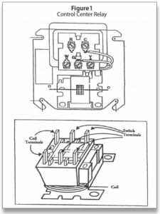
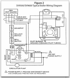
The system shown in Figure 2 is using a control center (transformer and relay) shown in Figure 1. The same control, when used on a forced warm air system, is called a “fan control center.” It is important to note that the wiring is different for a boiler versus a furnace. The use of a control center on a warm air furnace or boiler is a convenient place to connect wires and also makes for easier troubleshooting.
The transformer has the wiring connections attached. The “R” and “C” terminals are the only actual voltage connections. The other terminals are for wiring connections. The relay part of the control center is field replaceable. The best thing is to carry a SPDT relay, which can be used to replace another SPDT or SPST relay without any wiring changes in the junction box. Being able to stay out of the junction box is very important as the possibilities of connections coming loose are increased when you have to get into the “J” Box.
In addition to the “control center,” we have a Generation I SmartValve™ and a Honeywell D-892 vent damper. In Figure 2, the vent damper is shown with only the external wiring connections. It is sometimes difficult to imagine what is going on inside a control if the internal connections and components are not shown. I find that showing the internal operation of controls makes following the electrical path easier.
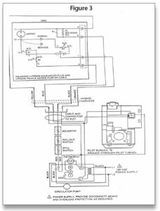
In Figure 3, we show the internal connections of the D892 vent damper. The sequence of operation we are going to follow is best understood using Figure 3. The purpose of the vent damper is to increase the efficiency of the equipment a little more by shutting down the standby loss from the boiler during the time when the thermostat is not calling. Anytime a vent damper is used, it must have an interlock circuit to ensure that the unit does not fire with the damper closed. This particular damper from Honeywell is powered closed and must have a continuous uninterrupted 24 volts at all times. When a call for heat takes place, the motor in the damper is de-energized and it will spring open. This, in turn, will activate the two N.O. sides of the switches (end switches).
In addition to power being required to the vent damper on a continuous basis, the SmartValve™ must also have an uninterrupted 24 volts at all times. When the SmartValve™ is used on a boiler application, the Electronic Fan Timer (EFT) output from the SmartValve™ is not used. The EFT output is only needed with a furnace.
Sequence of operation
The sequence of operation with this example is as follows:
1. Uninterrupted 24 VAC from R/C on Control Center is fed to SmartValve™.
2. 24 VAC to terminal 1 on the vent damper through the orange wire, through the right-hand side of relay Kl (closed) the NC set of S3 contacts to T2 through the motor to T1 and returning back to terminal 4 on the yellow wire. This powers the motor and damper is closed.
3. On a call for heat, the coil in the control center is powered and two sets of contacts close.
a. The left-hand set takes 120 VAC from L1 to Circulator Pump and back to L2.
b. The other set takes 24 VAC from R through spill switch, rollout switch and aquastat to terminal 2 on the vent damper.
4. The 24 VAC on 2 (black wire) goes to energize relay K1 in vent damper actuator and back to 4 on the yellow wire, the right-hand K1 switch is opened breaking power to the damper motor K1 switch now makes the left-hand side. The motor is now de-energized and the spring now opens the vent damper (mechanical action); the two normally open (N.O.) contacts close S1 and S2.
5. The relay stays powered through terminal 2 (black wire) during the entire call for heat unless one of the safeties opens.
6. The S1 and S2 (SPDT) set are in series and when the motor de-energizes and the spring opens the damper, they provide the path for 24 VAC through the left-hand side of K1 through S1 and S2 on the blue wire terminal to 3 on the damper powering the SmartValve™.
7. Now 24 VAC is fed out of terminal 3 on the vent damper to the interrupted leg of SmartValve™. The burner is now on.
8. When the call for heat ends, the control center relay coil is de-energized, as is also the K1 relay coil and the circulator shuts down. When K1 is de-energized, the K1 relay switches back to the right-hand side and the motor is powered closed. End switch contacts S1 and S2 are now tripped back to NC position.
9. Power is shut off to the interrupted leg of SmartValve™ and the burner shuts down.
It should be noted that switch S3 stays NC at all times unless the service switch is tripped; in that case it will de-energize the motor and the damper will now open manually.
The resistor R1 is to prevent power stealing programmable thermostats from energizing the damper when there is no call for heat. This is one of the phenomena of some power-stealing-type thermostats. ICM