Written on: October 10, 2022 by Timmie McElwain
Part 8, from the Sep/Oct 2022 Indoor Comfort
Parts 1 & 2, from the Jul/Aug and Sep/Oct 2021 Indoor Comfort can be found here.
Part 3, from the Nov/Dec 2021 Indoor Comfort can be found here.
Part 4, from the Jan/Feb 2022 Indoor Comfort can be found here.
Part 5, from the Mar/Apr 2022 Indoor Comfort can be found here.
Part 6, from the May/Jun 2022 Indoor Comfort can be found here.
Part 7, from the Jul/Aug 2022 Indoor Comfort can be found here.
As we look into some more modern systems and what specific problems they present, it is important to understand the basic fundamentals associated with these systems. Most of our modern heating equipment in some way or another involves electronics and the use of flame rectification as a safety and flame-proving system.
It doesn’t matter if it is a forced warm air furnace or a forced hot water boiler—the same basic system is used to perform safe ignition followed by consistent operation throughout the entire call for heat.
There are, however, different ways the system is applied from intermittent pilot application to direct spark ignition and including hot surface ignition (HSI). Each has its own distinct advantages and problems. We’ll now attempt to resolve those burner problems related to these systems, as well as offer corrections and diagnostics.
We will start with the basics and then continue to operation, typical problems, diagnosis, troubleshooting procedures and a final solution to a particular problem. It’s easy to jump to conclusions with these systems and just change parts to hopefully solve a problem. That is, however, time-consuming and costly.
I invite you to visit our new Facebook page Timmie’s Tips on Gas. I look forward to seeing you there.
We are presently doing a series on Honeywell Smart Valve™. We will pick up where we left off in the last article and cover Smart Valve™ The Third Generation. We will walk you through the step-by-step process of operation with these controls.
SmartValve™ Third Generation
The third generation of SmartValve™ became available to the original equipment manufacturers (OEMs) in late 1998/early 1999. It includes the SV9510/SV9520 and SV9610/SV9620.
The SmartValve™ works in conjunction with the Honeywell Electronic Fan Timer ST9160. It uses direct burner ignition line voltage igniters, such as the Norton 271, which has been used on HSI for many years. The new igniter used is the Norton 601.
The SV9540/SV9640 is also used with the EFT ST9160 control. It uses the same 24-volt igniter system used on SmartValve™ Generation I and II.
There is also a SmartValve™ SV9540Q used with Electronic Fan Time ST9162. This is a two-stage system that will be covered in a later discussion.
SV9510/SV9520; SV9610/SV9620 SmartValve™ System Controls
Application
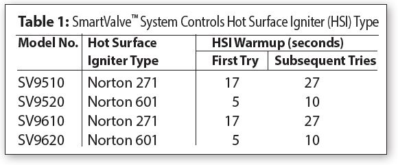
The SV9510/SV9520 and SV9610/SV9620 SmartValve™ System Controls combine gas flow control and electronic direct main burner ignition sequencing functions into a single unit. The ignition source is a 120V HSI lighting the main burner flame. Two types of 120V igniters may be used, as seen in Table 1.
The control provides all gas ignition safety functions by controlling gas flow, ignition source and a 120 VAC combustion air blower. The control also monitors the appliance airflow-proving switch and limit string to assure proper appliance operation.
The SmartValve™ System Controls provide pre-purge, post-purge and timed trial for ignition with multiple ignition trials and auto reset from lockout. Diagnostic LED indicates system status.
The control communicates directly with the ST9160 Electronic Fan Timer (EFT) in typical forced warm air furnace applications. It will also interface with the 208907 Terminal Board, providing compatibility with power-stealing thermostats. Alternately, it directly interfaces with the appropriate power supplies and a system thermostat for additional appliance applications. When controlled directly by a thermostat, the control does not provide a post-purge function, as power to the control is removed when the thermostat’s call for heat ends.
This system is suitable for a wide range of fan-assisted, combustion, gas-fired appliances including furnaces, rooftop furnaces, boilers, unit heaters, infrared heaters, water heaters and commercial cooking appliances.
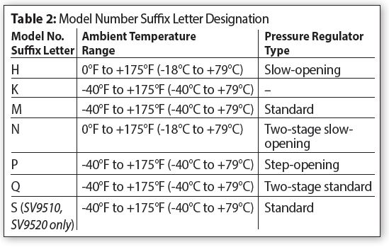
The specific application of the SmartValve™ System is the responsibility of the appliance manufacturer. See Table 2 for temperature ranges and regulator types.
Line voltage polarity sensing models monitor the line voltage input connection to assure line voltage polarity is correct. If line voltage polarity is incorrect, the LED diagnosis code will flash and the control will not respond to the call for heat. These models also provide added LED diagnostic codes (“6+”) to indicate the reason the control has moved to the lockout state.
Depending on models, various timings are available, such as 15 or 30 seconds pre-purge; post-purge five seconds (typical depending on model; this is not available when the SmartValve™ is connected directly to the thermostat); five, seven or nine seconds trial for ignition; 60-minute soft lockout; three retries; four trials before lockout. The other unusual feature is that the draft inducer is now controlled from the SmartValve™; depending on the version, this is accomplished by either interrupting the 120 volts or 24-volt signal. This will be defined as each diagram is discussed.
The capacities on SV9510, 20 and 40½” x ½” 200,000 BTUs maximum and on the SV9610, 20, 40¾” x ¾” is 415,000 BTUs.
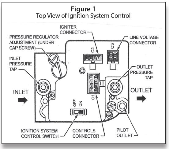
Figure 1 is an illustration of the top view of the valves. The C3 connector is for 120-volt power, and this is also the feed for the draft inducer. The C2 connector is for the 120-volt HSI, either the Norton 271 Silicon Carbide in the case of the SV9510, or the Norton 601 120 volt Silicon Nitride Igniter used only with the SV9520 model. The C1 connector is the low voltage 24-volt AC hookup.
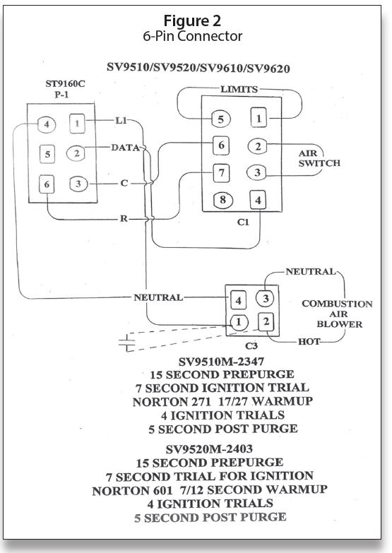
The designation of pin numbers for the C1 and C3 connectors on the SmartValve™ and the 6-pin connector on the ST9160 Electronic Fan Timer are illustrated in Figure 2.
Converting Ignition System Control
From Natural Gas to LP Gas Application (or LP Gas to Natural Gas Application)
Always change the main burner orifices as provided by the manufacturer of the equipment being converted. Ignition system controls are factory-set for natural (and manufactured) or LP gas. Do not attempt to use an ignition system control set for natural (manufactured) gas on LP gas, or an ignition system control set for LP gas on natural (manufactured) gas.
Ignition system controls with standard or slow opening regulators (SV9510M, H/ SV9520M, H, K) can be converted from one gas to the other with a conversion kit (ordered separately). Order part No. 393691 to convert from natural (manufactured) to LP gas; order part No. 394588 to convert from LP to natural (manufactured) gas.
Two-stage ignition system controls (those with N and Q suffix letters) can be converted using a conversion kit (ordered separately). Order part No. 396021 to convert from natural (manufactured) to LP gas; order part No. 396025 to convert from LP to natural (manufactured) gas.
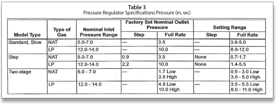
IMPORTANT: Ignition system controls with step-opening regulators (SV9510P/ SV9520P) cannot be field-converted to LP or natural gas. See Table 3 for pressure settings for valves.
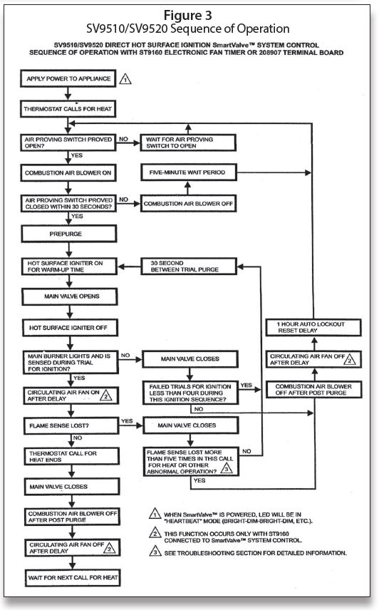
SV9510/SV9520 Sequence of Operation
Figure 3 is the sequence of operation for the SV9510 and SV9520 SmartValve™.
Training
Finally, I love to teach and would love to have you come and join us for some training. We also conduct seminars on the following topics and many others:
Five-Day Course
• Fundamentals of Gas
• Circuitry & Troubleshooting
• Hydronic Controls
• Electric Ignition Systems
• Advanced Electric Ignition Systems
One-Day Course
• Powerpile Systems
Three-Day Course
• Combustion Testing Design Gas Equipment
• Conversion Burners
Four-Day Course Designed for Your Specific Need
• Modulating/Condensing Boilers
For more information, call 401-437-0557 or write to:
Gas Appliance Service Training & Consulting
42 Village Drive, Riverside, RI 02915.
E-mail: timmcelwain@gastcri.com. ICM