Written on: December 12, 2022 by Timmie McElwain
Part 9, from the Nov/Dec 2022 Indoor Comfort
Parts 1 & 2, from the Jul/Aug and Sep/Oct 2021 Indoor Comfort can be found here.
Part 3, from the Nov/Dec 2021 Indoor Comfort can be found here.
Part 4, from the Jan/Feb 2022 Indoor Comfort can be found here.
Part 5, from the Mar/Apr 2022 Indoor Comfort can be found here.
Part 6, from the May/Jun 2022 Indoor Comfort can be found here.
Part 7, from the Jul/Aug 2022 Indoor Comfort can be found here.
Part 8, from the Sep/Oct 2022 Indoor Comfort can be found here.
As we look into some more modern systems and what specific problems they present, it is important to understand the basic fundamentals associated with these systems. Most of our modern heating equipment in some way or another involves electronics and the use of flame rectification as a safety and flame-proving system.
It doesn’t matter if it is a forced warm air furnace or a forced hot water boiler—the same basic system is used to perform safe ignition followed by consistent operation throughout the entire call for heat.
There are, however, different ways the system is applied from intermittent pilot application to direct spark ignition and including hot surface ignition (HSI). Each has its own distinct advantages and problems. We’ll now attempt to resolve those burner problems related to these systems, as well as offer corrections and diagnostics.
We will start with the basics and then continue to operation, typical problems, diagnosis, troubleshooting procedures and a final solution to a particular problem. It’s easy to jump to conclusions with these systems and just change parts to hopefully solve a problem. That is, however, time-consuming and costly.
I invite you to visit our new Facebook page. I look forward to seeing you there.
We are presently doing a series on Honeywell SmartValve; in this article, we will cover SmartValve Third Generation and walk you through the step-by-step process of operation with these controls.
SV9510/SV9520 Sequence of Operation
Figure 1 is the sequence of operation for SV9510 and SV9520 SmartValve. The various diagrams featured in this article will show you the circuits involved.
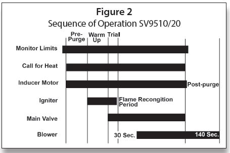
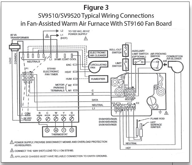
Referring to Figure 1 and Figure 2 for the Sequence of Operation and to Figure 3 for a diagram, let’s go through the Sequence of Operation.
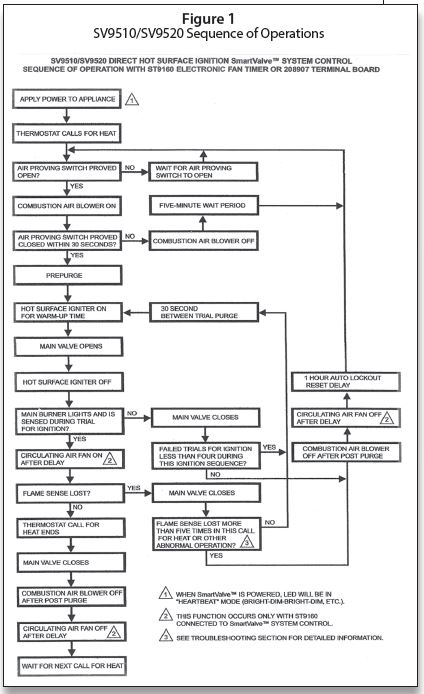
When power to both 120 VAC and 24 VAC is applied to the system, the LED on the SmartValve will be pulsing “in the Heartbeat mode”—bright-dim-bright-dim, etc. L1 (Hot) is fed to L1 on the EFT. Then 120 VAC is fed from XFMR (transformer) to an external 40 VA or 50 VA transformers, depending on which valve. From the transformer, 24 VAC is fed to the 24VAC/Com terminals on the EFT.
The dotted lines in Figure 3 are my additions to illustrate the printed circuit board feed from L1 to P1-1 120 VAC, and from neutral to P1-4, as well as the 24 VAC (Hot) from terminal 24VAC to P1-6 and the common (COM) to P1-3. The ST9160 Electronic Fan Timer will be covered in a later section.
The setup for this wiring shown in Figure 3 has the 120 VAC to the SmartValve interrupted and 24 VAC is fed direct on the “R” wire to C1-7 and the “C” to C1-6 on the SmartValve. On a call for heat, a circuit is completed through R and W on the ST9160 the air-proving switch, which must then prove open in 30 seconds. If it does, then 120 VAC is fed from P1-1 to C3-2 and back on neutral from C3-4 to P1-4. Then 120 VAC is fed from C3-1 to the Combustion Air Blower and back to neutral on C3-3. Then the prepurge begins.
At the end of the prepurge, the HSI warm-up starts. The igniter warm-up time for the Norton 271 (used with SV9510) is 17 seconds on the first try and 27 seconds on subsequent tries. The Norton 601 (used with SV9520) warm-up is five seconds on the first try and then 10 seconds on subsequent tries.
The main valve opens and ignition takes place. The flame rod proves the burner flame and the DATA signal is fed from C1-4 to P1-2 to start the fan-on time sequence. The fan will usually come on in 30 to 60 seconds.
When the call for heat ends, and R and W breaks, power to the Combustion Air Blower ceases after post-purge. The air proving switch opens and the DATA signal ceases; the Electronic Fan Timer goes to the dip switch set fan-off run time. At the end of that time, everything is ready for the next call for heat.
Figure 4 shows how the 208907 terminal board allows compatibility with power-stealing thermostats. Many of the control boards cannot be used with power-stealing thermostats unless there is an isolating relay used or a 100 ohm 10 watt resistor placed across W and C.
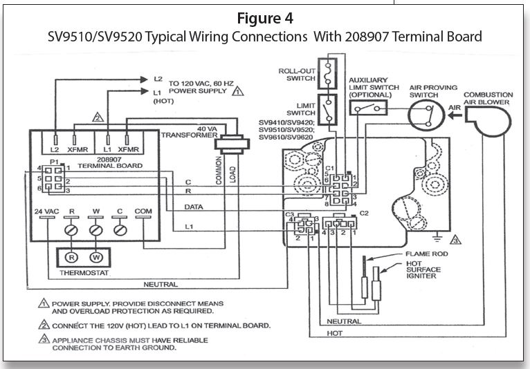
Figure 5 shows a typical wiring diagram with a Forced Hot Water System using a R8285D Honeywell Control Center. With this setup, the 120 VAC is fed direct from the junction box to C3-2 (Hot)/C3-4 (Neutral); in this case, the 24 VAC is interrupted.
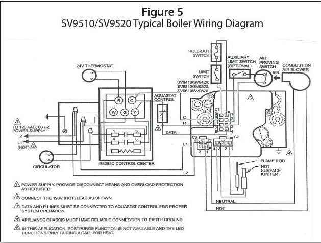
L1 Hot is also fed to Pin 3 on the R8285; also, 24 VAC is fed to Pin 4. On a call for heat from the thermostat, 24 VAC is fed from “R” through the thermostat to “G,” then to the relay coil and back to “C.” This brings in the two sets of relay contacts—1–3 sends 120 VAC to the circulator; 4–6 takes 24 VAC from “R” to “Y” through the aquastat control (high limit) to the R and DATA wire C1-7 and C1-4 (DATA). The sequence after that is the same as the sequence for Figure 3.
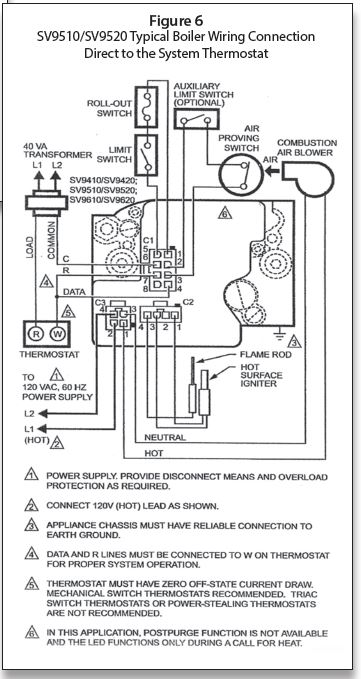
Figure 6 is an example of wiring direct to the thermostat. This setup could also be used for a steam system by adding a Low Water Cut-Off and Pressuretrol in place of the limit switch.
The 24 VAC is again interrupted and the 120 VAC is fed direct to C3-2 and C3-4. In many instances, a jumper from C1-4 to C1-7 may accomplish the wiring from the DATA to “R” wire. Pay particular attention to the triangle notes 1–6 in Figure 6.
In the next article we will discuss troubleshooting the SmartValve Third Generation. ICM