Written on: December 15, 2025 by Timmie McElwain
This is the third in a series of articles on Honeywell S9301A Integrated Boiler Control, which provides operation of a high efficiency gas boiler with a combustion air blower and a combination hot surface igniter/flame sensor. We listed all the features of this control in the July/August 2025 issue of Indoor Comfort Marketing, and reviewed the sequence of operation in the September/October 2025 issue.
In this issue, we will go over troubleshooting for this control.
The S9301A Integrated Boiler Control is fully certified by the American Gas Association (AGA) and the Compressed Gas Association (CGA) as an Automatic Gas Ignition Device. It provides control of a high efficiency gas boiler with a combustion air blower and a combination hot surface igniter/flame sensor, and is intended for residential boilers only and not for use with a vent damper. Other applications require a review and written approval from Honeywell Residential Design Engineering; contact your Honeywell Sales Representative for assistance.
It provides:
1. Sequencing of ignition and burner operation
2. Two additional trials for ignition if initial light-off is unsuccessful
3. Wiring terminal board for all electrical connections
4. Control of circulator pump and combustion blower motors
5. Monitoring of aquastat and auxiliary limits to ensure proper water temperature and of the air-proving switch to ensure proper sequencing of combustion air before the ignition sequence starts
6. Continued circulator pump operation during lock-out as long as thermostat calls for heat
7. Four LED lights that indicate operating mode and help identify the problem source during troubleshooting
8. Keyed plugs for wiring connections
Troubleshooting the Honeywell S9301A Integrated Boiler Control
Before attempting to troubleshoot this control, it is important to be aware of different behaviors upon failure. The Quick Check we will discuss later will make much more sense if the various problems and their behaviors are understood.
Failure to Light: Lock-out
Should the main burner fail to light within the initial trial for ignition period, the control moves into its retrial mode. Two additional ignition trial sequences may occur. Each consists of a 30 second between-trial purge (inter-purge), followed by a normal ignition sequence, including the 15-second pre-purge, igniter warm-up and trial for ignition.
However, the igniter warm-up time on a retrial is 30 seconds, rather than the 20 seconds of the initial ignition sequence. If the main burner lights on either retrial, appliance operation continues normally. If the main burner does not light during any of the three ignition sequences, the control will go into lock-out.
The valve will be turned off immediately; the inducer will be turned off after a 30-second post-purge; and the valve/flame LED will flash to indicate the reason for lock-out. Note that the circulator will continue to run during lock-out, as long as the call for heat remains.
Combustion Air Flow Problem: Lock-out
Combustion air flow is continually monitored during light-off and run using a single-pole, single-throw (SPST) air switch. Upon initial call for heat, the control will wait for up to 45 seconds to allow the pressure switch to indicate no air flow (contact open), before turning on the combustion air blower (inducer).
When the switch contacts are open, the combustion blower is powered and the control waits up to five minutes for air flow to be established (contact closed). When the contact closure proves air flow, the control begins the 15-second pre-purge period with normal ignition sequence following.
If the air switch contacts do not sequence properly within the times stated above, the control will lock-out with the inducer off. The purge LED will flash, indicating an air flow problem as the reason for lock-out.
Again, the circulator continues to run as long as the thermostat calls for heat. If combustion air flow is lost while the burner is firing (air switch contacts open), the control will immediately shut off the gas valve. The inducer will stay on for a 30-second post-purge.
Then, if the call for heat remains, the control will wait five minutes for air flow to return. If air flow is not proved within this time, the control will lock-out, as noted above. If air flow is proved within the five-minute period, a normal ignition cycle will begin.
Recovery from Lock-out
Recovery from any lock-out requires a manual reset, which is readily done by removing and reapplying either the thermostat’s call for heat or power to the control.
Aquastat/Limit Action
The aquastat and auxiliary high limit circuit is continually monitored while the appliance is running. If the aquastat or limit opens, the gas valve is immediately turned off.
The blower (inducer) runs for the 30-second post-purge and is then switched off. The circulator continues to run with the call for heat. If the aquastat or limit remakes, the control goes into a normal light-off sequence.
Flame Failure: Recycle
If an established flame signal is lost while the burner is operating, the control will immediately turn off the gas valve and go into a 30-second post-purge.
The control will then attempt to relight the appliance, beginning with the 15-second pre-purge, warm-up and ignition trial. As on the original call for heat, the control will make up to three attempts to light the appliance, with extended igniter warm up times on the second and third ignition trials.
If the appliance does not light, the control will go into lock-out as noted in the “failure to light” paragraph in the previous column. If the appliance relights, normal operations will resume.
Quick Check for Honeywell S9301A
1. Shut off the power. Disconnect all plugs into the terminal board.
2. Turn the power back on.
3. Follow the sequence of operation.
4. Check for 120 volts of alternating current (VAC) on the plug-in to the 120 VAC on the board. If you have 120 VAC, plug back into the board. (Pins 1 and 3 on CN7)
5. Check output from the transformer primary for 120VAC (Pins 1 and 3). If you have 120 VAC, plug back in CN3.
6. Check for 24 VAC on the plug into 24 VAC transformer. If 24 VAC, plug in CN2.
7. The system is now ready to go through a call for heat.
8. The circulator and the inducer come on at the same time. Check for 120 VAC out on CN4 and CNS Pins 1 and 3.
9. The system will go through pre-purge, then should have 120 VAC at CN1 for the igniter. Plug in the igniter if 120 VAC is present. The system may need to be recycled; this would also be a good time to ohm out the igniter.
10. With the thermostat calling and the igniter energized, the gas valve should open. If there is no power to the gas valve 24 VAC, check the air-proving switch or replace the 89301.
11. Flame should prove and the system should run until the thermostat is satisfied.
12. When the thermostat is satisfied, the circulator will shut off. There should continue to be 120 VAC to the inducer for the post-purge period.
NOTE: If at any time you fail to get power out on the terminals on the S9301A, then replace S9301.
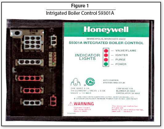
Integrated Boiler Control Lights
• Power: Green light glows whenever the integrated boiler control is powered.
• Purge: Red light glows during pre-, post- and between trial purges. It blinks if the control locks out because of a problem with combustion air flow, as long as the thermostat is still calling for heat.
• Igniter: Red light glows when the igniter is powered.
• Valve/Flame: Red light glows whenever the gas control is open. It blinks if the control locks out because of a flame failure or failure to light, as long as the thermostat is still calling for heat. ICM