Written on: February 14, 2022 by Alan Mercurio
The terms “single-stage” and “two-stage” refer to the separation of the suction and the pressure function within the pump. In a single-stage pump, the same set of gears is used for the suction and pressure delivery of the oil. The two-stage pump has one set of gears to pull the fuel from the tank and the other is to deliver it under pressure to the nozzle. You can push oil quite a distance, but pulling it back is the challenge.
You can download the very useful US Installation and Service Manual from Suntec’s website.
Some helpful notes
Running the vacuum should not exceed the following specs:
 Rule of thumb:
A quick rule to check an installation is to figure 1″ of vacuum for every foot of vertical lift, and 1″ of vacuum for every 10′ of horizontal run.
The following information is based on the information supplied by fuel pump manufacturer Suntec Industries Inc., and based on a model A-700 type pump at three gallons per hour (GPH) and 3,450 rotations per minute (rpm).
Sizing & diagnosing with calculations
The line sizing that we are about to do is based on the following formula and legend:
• L = Total length of fuel line
• Q = Fuel line diameter (⅜” = .0086) x GPH (if using a two line system figure total fuel pump GPH)
• H = Total lift from the bottom of the tank to the middle of the fuel unit x 0.75
• V = Vacuum hg. Inches mercury
L x Q =? + H = V
Note: The factor 0.75 will always be the formulated number multiplied with (H). All of the fuel line diameter equations are based on the following data:
• 3/8″ fuel line = .0086
• 1/2″ fuel line = .00218
• 5/8″ fuel line = .000785
The following formula will be used in the examples:
Height x 0.75 =? -6 =? Divided by GPH (gallons per hour) =? Divided by .0086 = Length
Note: If the tank is above the fuel unit, change the -6 to +6. Also remember that fittings, valves and filters will reduce total length allowed.
Example # 1:
10′ x .75 = 7.5 -6 = 1.5 divided by 1.00 GPH = 1.5 divided by .0086 = 174″ of 3/8″ OD fuel line. In this example, the fuel tank is below the fuel unit, and you would need to use a two-line configuration, or my preferred choice would be to use a deaerator.
With regard to Example #1, by using the following formula below, you can confirm that you will or will not be within the manufacturers’ recommendations for maximum vacuum and also determine the anticipated vacuum, less the fittings and filters. You’ll also discover the length and size of the fuel line that should or should not be used.

Rounding up 8.9964 to 9″ of vacuum is 3″ higher than the manufacturer recommends for a single pipe configuration. It may be the reason why we may choose to install a deaerator (see Figure 1).

Figure 1
You may wonder, why we don’t utilize a two-pipe configuration. Toward the end of this article, I’ll share with you how you could, what I’ve learned over the years and why my choice is a deaerator instead of a two-pipe system.
For the record, you also could install a Model B-800 two-stage fuel pump that can maintain 17″ of vacuum or increase the size of the fuel line, whichever would be more prudent and cost-effective.
Note: Once again please remember, when adding filters and fittings to these examples, you’ll need to use less fuel line or a different pump. Trust me, the more you use these formulas, the easier they get.
Vacuum gauges and diagnosing
This section will give you the anticipated vacuum you should expect when you know the given line length, diameter and GPH, plus the height from the bottom of the tank to the middle or shaft of the fuel unit. Let’s look at an example of a manufactured home 14′ x 70′. Let’s say the fuel line is 50′ of 3/8ths line from the tank to the fuel unit, and the lift is about 4′. If you haven’t already, you’re going to want to make a vacuum gauge (see Figure 2) a part of your tool arsenal.

Three inches of vacuum is well within the limits of the fuel unit, however if the fuel unit constantly needs to be bled, and the vacuum is 1″, this would tell you that you have an air or oil leak. A vacuum higher than 3″ would indicate there is a restriction in the system caused by a kinked or plugged line, plugged fuel filter or fuel gelling, etc.
Fuel pump pressure regulating valves
Since the pump is directly connected to the burner motor by a burner coupling, the oil delivered and its pressure will be constant in relation to the rpm of the burner motor. This is why a device to adjust the pressure to the nozzle is required. This is called the “pressure-regulating” valve (see Figure 3).
The functions of the pressure-regulating valve are:
• To prevent any oil from reaching the nozzle before it comes up to atomizing pressure (usually above 70 pounds per square inch [psi]).
• To maintain a constant operating pressure, 100 psi or higher (a constant pressure will allow for a uniform flame, free of noise and pulsation, providing everything else is in order).
• To provide a quick, clean cut-off of fuel as the burner goes off (the valve must also prevent any oil from dripping into the combustion chamber in the off cycle to prevent after-fire and after-drip).

Figure 2
To check the pump pressure, cut-off pressure and the overall integrity of the fuel pump, you would install a fuel pump pressure gauge (see Figure 4) in the pressure port opening or by disconnecting the nozzle line from the draw assembly and connecting it to your fuel pump pressure gauge.
Once the gauge is connected, you would run the burner and take note of the pressure reading on the gauge. For example, when the pressure is 100 psi and the unit shuts off, the indicator on your gauge should not drop more than 20% of the running pressure of the fuel unit—in this case that would be 80 psi and this would be a good cut-off pressure. If it were to drop below 80 psi before condemning the fuel pump, check to make sure all your fittings are tight, especially on your fuel pump gauge. This would be the time to use the vacuum gauge that we discussed earlier. See Figure 2.
As the motor comes up to speed, more oil than needed is being delivered to the nozzle. To maintain the constant oil pressure desired, the regulating valve opens and closes a bypass port that bypasses the excess oil. In a one-pipe system, the excess oil is bypassed back to the suction side of the fuel pump. This is known as an internal bypass. In a two-pipe system the oil is returned to the fuel tank. This is known as an external bypass.
The desired pump pressure at the nozzle is achieved by adjusting the tension of the spring on the regulator, making it easier or harder for the valve to uncover the bypass port.
It’s worth mentioning that for even better overall performance, newer fuel units such as the R.W. Beckett Cleancut or Suntec A2VA-3006 are the choice of most techs nowadays.
Lessons learned
As promised, I’ll end this article sharing what I’ve learned over the years and why my choice would be to install a deaerator instead of a two-pipe system.
First, I agree that, sadly, deaerators are misapplied in a number of installations, which is why I teach my students that when there’s a suction leak, find it and repair it. In that instance, deaerator installation is just a Band-Aid on the problem with a serious risk of causing environmental contamination.
When you have a high lift / long run, it is likely to cause cavitation that will lead to air-bound fuel units and has nothing to do with suction leaks. The deaerator will overcome this and prevent the cavitation, and the benefits, in my humble opinion, outweigh the two-line system I was taught about 30+ years ago. Also:

Figure 3
1. With a two-line system operating with the total gear suction capacity of the fuel unit, you’ll find the need to replace oil filter/s and strainers more frequently.
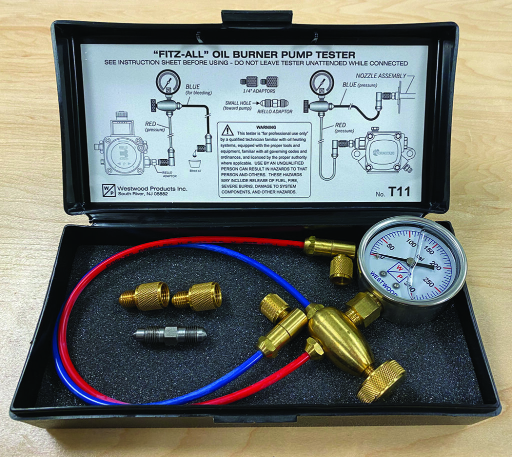
Figure 4
2. With a two-line system, your return line is considered an unmonitored line and if there’s a leak, it will not cause a lock-out condition and likely not be discovered until the homeowner is selling the home and a soil sample is taken.
3. With a two-line system, the oil in the return line is warmer than when it came in through the supply line, and once it’s outside, can create condensation that makes its way back to the oil tank. This promotes sludge caused by bacteria that grow in fuel oil.
4. With a two-line system, water in the tank could potentially freeze, block the return line and cause the seal in the fuel unit to rupture.
5. With a two-line system, the return line increases the contact time with yellow medals that increases degradation of the product and surrounding materials (I got that one from my good friend Robert C. O’Brien).
Deaerators not only overcome the cavitation issue, but eliminate the concerns that come with having a return line. ICM
Alan Mercurio, Lead Technical Trainer & Assistant Director PPATEC, a division of the Pennsylvania Petroleum Association. Email: amercurio@papetroleum.org; phone: 717-939-1781 ext. 101 or on PPATEC’s Facebook Page.