With today’s flame retention burners and smaller combustion chambers, it’s crucial to understand the effects that increasing fuel pump pressure can have on a system. This would include possible incomplete combustion that could lead to the production of carbon monoxide (CO).
Tolerances
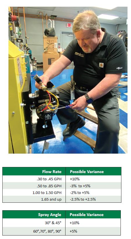
Something you should know is the tolerances nozzles fall within. For example, if you had a system with a maximum firing rate of 1.20 gallons per hour (GPH), and you decide it would be better to install a 1.00 GPH nozzle, you increase the fuel unit pressure to 145 pounds per square inch (PSI) and you will be back to 1.20 GPH with the smaller nozzle. Or will you?
Nozzles from 1.00 GPH to 1.50 GPH can have
a tolerance of -2% to +5%.
If the 1.00 GPH nozzle you installed was +5% at 145 PSI, your actual firing rate would be 1.26 GPH. Again, this could lead to a system cycling on high-limit, and/or worse yet, the incomplete combustion that will lead to the production of CO.
Now, with a better understanding, if you were increase the pump PSI to only 120 PSI, you will find this will only bring the 1.00 GPH nozzle to 1.10 GPH. Even if it was over by 5%, it would still only be approximately 1.155 GPH, still well under the maximum firing rate.
Spray pattern
Here is something else to think about. Did you know when you increase your pump pressure the spray pattern gets shorter and the angle will become wider?
This means your 80° nozzle may have just become an 84° nozzle. You may have done this because the flame was impinging on the back wall of the chamber. Unfortunately, now it may be impinging on two sides of the chamber. In this, case you may have wanted to change the nozzle to a 70°.
These are the reasons why it’s so important to understand this and to always, after any adjustments are made to the burner, including changing the nozzle, perform a combustion analysis. ICM
Alan Mercurio, Lead Technical Trainer & Assistant Director PPATEC, a division of the Pennsylvania Petroleum Association. Email: amercurio@papetroleum.org; phone: 717-939-1781 ext. 101 or on PPATEC’s Facebook Page.
There is an ongoing opportunity to test and utilize products from our industry. This article was written for the betterment of our industry and, most importantly, as an opportunity for me to thank my coworker Jessica Reeder for her service to our country as an E-5 Staff Sergeant in the U.S. Air Force.
None of this would have been possible without a number of folks from in our industry. Thank you to:
• Energy Kinetics—Roger Maran, Brian Kiernan, Jay McCay
• R. W. Beckett—Curtis Martin
• Buchanan & Erb (Fuel Oil & Service Provider)—Dwayne Weller and Jon Daniels
My co-worker Jessica Reeder is a consultant who has worked with the Pennsylvania Petroleum Association (PPA) for more than four years to assist with the Education Program as a Program Administrator and as a Membership Support Specialist. Jessica is an Air Force veteran with a Bachelor’s degree in Accounting from the University of Maryland, from which she graduated Magna cum Laude. She believes that the training PPA Technical Education Center (PPATEC) offers, and the services PPA provides to members, are vital to the energy industry.
The project
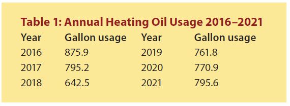
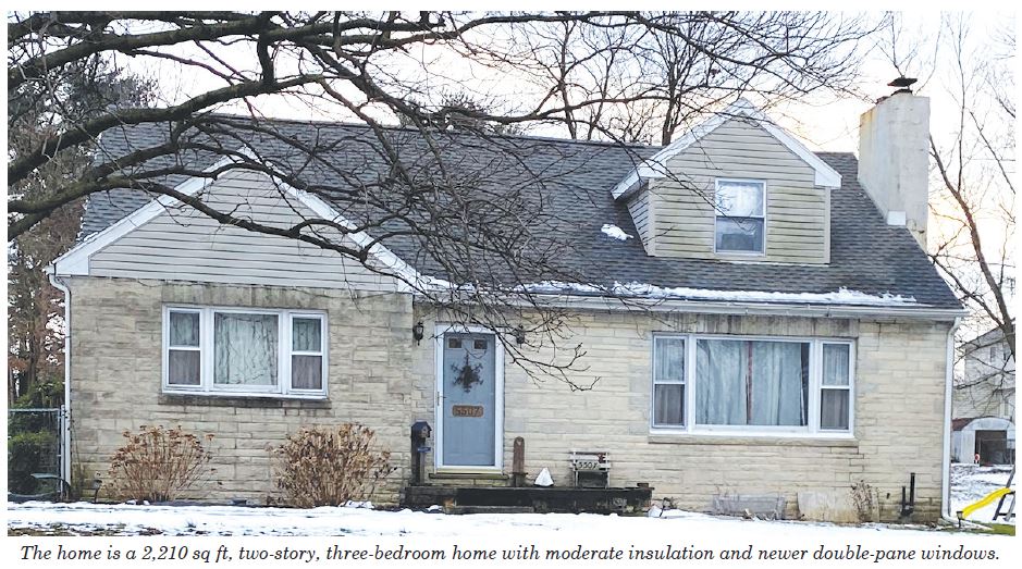
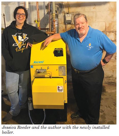
Oil Tech Talk, an online forum and Facebook page for technicians, coordinated and continues to oversee this project and collect valuable data. Jessica’s home is a 2,210 sq ft, two-story, three-bedroom house with moderate insulation and newer double-pane windows. On Jan. 14, a group of us met at Jessica’s home to install a new energy-efficient Ascent boiler with a plate exchanger for the domestic hot water. Our goal was to see how much we could reduce energy costs—to heat this home and provide hot water—for the family of four. The home has been consuming an average of 800 gallons of heating oil (+/- 50 gallons) a year from 2016–2021.
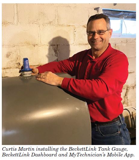 With the seven years of fuel usage history available, I will record the savings and share them in Part 2. I will collect this data remotely with the BeckettLink Tank Gauge, BeckettLink Dashboard and MyTechnician’s Mobile App, which will make tracking and monitoring the savings easy. These were installed by our good friend Curtis Martin, who spent the day with us helping with the installation.
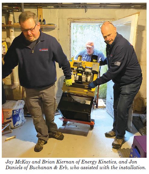
I’d also like to acknowledge Jay McKay and Brian Kiernan of Energy Kinetics, and Jon Daniels of Buchanan & Erb, who really did the bulk of the work during this project.
 The savings There are three key advancements that I believe will provide a significant amount of savings for Jessica and
her family.
1. The Ascent is equipped with Hydrostat that allows you to adjust settings to match your individual lifestyle. For greater savings, you can select a Smart Learning Mode at the touch of a button for on-demand operation. If you don’t use hot water overnight during the summer, your boiler doesn’t have to run. The Ascent Hydrostat is so smart that it learns weekly routines and is ready when you typically need hot water—and it saves your energy when you don’t need it.
2. The Ascent is also equipped with a plate heat exchanger that delivers continuous hot water via a tank-less coil boiler; its permanent, non-stick coated surfaces prevent lime and mineral build up for exceptional long-term performance in hard water applications.
3. The innovative design and engineering of this boiler’s spiral heat exchanger and its materials produce more hot water that lasts longer than the previous boiler with a tank-less coil, while efficiently providing warmth and comfort in the Winter.
I am sharing a picture of me and Jessica above; as you can see, she is pretty happy with her new energy-saving heating system, and I’m betting she’s going to be even happier when she and her family see how much money this will save them. ICM
Alan Mercurio, Lead Technical Trainer & Assistant Director PPATEC, a division of the Pennsylvania Petroleum Association. Email: amercurio@papetroleum.org; phone: 717-939-1781 ext. 101 or on PPATEC’s Facebook Page.
We sure have come a long way from the old Honeywell T87 Thermostat and the combination Fan & Limit control. I’d like to share some of the things I’ve learned and perhaps some you may not have yet learned yourself. Remember, with an open heart and open mind you can learn more each day. After more than 30 years in the trade, I’m still learning.
I’ll begin with the thermostats. Years ago when installing a new device, we often checked to make sure the heat anticipator was set correctly to connect to, or to replace, the thermostat (Figure 1). The heat anticipator was a small electrical resistance heater that fooled the thermostat into thinking it was warmer in the room than it actually was. You needed to make sure that the heat anticipator was set to match the amps from the thermostat’s control device. You could have also used an ammeter connected to the wires at the thermostat—this would’ve shown you the amp reading; you would have then matched the heat anticipator to that reading.

With today’s thermostats, from the very basic to the programmable, we have Cycles Per Hour (CPH). We adjust CPH via dip switches (Figure 2) depending on the model of programmable thermostat. Instead of setting the CPH via dip switches, we set that from within the programming/setup mode.

The thermostat is designed to control temperature to +/- 1°F. The cycle rate setting is one factor that helps the thermostat maintain a temperature setting. How often the heat turns on and off depends on many factors, including the type of heating system or how much the system needs to run to maintain your temperature setting (in other words, how cool or cold it is outside).
A typical forced air system will cycle about five times in an hour—this is normal. A typical hot water system should cycle less than that. Every heating system type will deliver heat to the house at a slightly different rate. Some thermostats provide the flexibility to set the cycle rate to match your specific heating system, whether it is forced air, high efficiency forced air, electric forced air or baseboard hot water. The thermostat’s operating manual will tell you to match the cycle rate setting to your heating system type. For those thermostats that learn your usage, the CPH sets a target point for the learning algorithm.
AIR
Here’s another acronym for you, AIR. It stands for Adaptive Intelligent Recovery. This is where that algorithm comes into play. Through the algorithm, AIR enables the thermostat to “learn” how long a heating system and air conditioner take to reach the programmed temperature settings. It will then start the system early enough for it to reach that preferred temperature on schedule.
For example, if the thermostat was programmed to bring the temperature up to 70°F at 7:00 a.m., it might come on around 6:45 a.m. to gradually reach that temperature efficiently. As it gets colder outside, the thermostat will recognize (learn) that it took longer to reach 70°F at 7:00 a.m., and the next morning it would start a little earlier, maybe 6:35 a.m. Once it warmed back up outside, the thermostat would resume its normal mode of operation.
It’s important to understand these things, as little as they may seem. It’s equally important to educate consumers—our customers—on things of this nature. If they are not aware of AIR, they may think something is wrong with their thermostats and you’ll end up going out on unnecessary service calls. If you explain ahead of time that a system automatically defaults to AIR upon installation, you may also learn it’s not a feature they wish to utilize and can turn it off for them during thermostat installations.
Electronic fan board
Another item that has come a long way in our industry is the electronic fan board. We’ve gone from electronic fan boards that offer the basic control of turning the burner and blower “On” and “Off” to electronic fan boards that can also control multi-speed blowers, ECM blowers, humidifiers and both heat and AC.
Today’s advances in electronic board technology have really stepped up their game. Universal electronic fan boards are not new, but the type seen in Figure 3 offer much more—such as being adaptable for multispeed PSC or ECM driven blowers, diagnostic lights for troubleshooting, status lights, supply and return duct temperature monitoring, fuel tank level monitoring and much more.

With its Wi-Fi capability, a technician can access the system from a device wherever they may be (Figure 4), perform some initial troubleshooting and test run cycles without even being on-site. This feature is very valuable, because information is also available from the technician’s device, identifying the model and serial number of the appliance. Whatever component the tech believes he/she may need, it can be packed before traveling to the customer’s home. We have come a long way with technology and I’m looking forward to what’s next.

Thank you
This wraps up the series of articles I wanted to share with you regarding change and acceptance in today’s industry, and the technologies that come along with them. Thank you for taking the time to read my articles and allowing me to share my thoughts and perspective and thank you to our friends at Indoor Comfort Marketing for giving me the platform to do so. I look forward writing more articles later this year; I hope you all look forward to reading them. ICM
Alan Mercurio, Lead Technical Trainer & Assistant Director PPATEC, a division of the Pennsylvania Petroleum Association. Email: amercurio@papetroleum.org; phone: 717-939-1781 ext. 101 or on PPATEC’s Facebook Page.
The terms “single-stage” and “two-stage” refer to the separation of the suction and the pressure function within the pump. In a single-stage pump, the same set of gears is used for the suction and pressure delivery of the oil. The two-stage pump has one set of gears to pull the fuel from the tank and the other is to deliver it under pressure to the nozzle. You can push oil quite a distance, but pulling it back is the challenge.
You can download the very useful US Installation and Service Manual from Suntec’s website.
Some helpful notes
Running the vacuum should not exceed the following specs:
 Rule of thumb:
A quick rule to check an installation is to figure 1″ of vacuum for every foot of vertical lift, and 1″ of vacuum for every 10′ of horizontal run.
The following information is based on the information supplied by fuel pump manufacturer Suntec Industries Inc., and based on a model A-700 type pump at three gallons per hour (GPH) and 3,450 rotations per minute (rpm).
Sizing & diagnosing with calculations
The line sizing that we are about to do is based on the following formula and legend:
• L = Total length of fuel line
• Q = Fuel line diameter (⅜” = .0086) x GPH (if using a two line system figure total fuel pump GPH)
• H = Total lift from the bottom of the tank to the middle of the fuel unit x 0.75
• V = Vacuum hg. Inches mercury
L x Q =? + H = V
Note: The factor 0.75 will always be the formulated number multiplied with (H). All of the fuel line diameter equations are based on the following data:
• 3/8″ fuel line = .0086
• 1/2″ fuel line = .00218
• 5/8″ fuel line = .000785
The following formula will be used in the examples:
Height x 0.75 =? -6 =? Divided by GPH (gallons per hour) =? Divided by .0086 = Length
Note: If the tank is above the fuel unit, change the -6 to +6. Also remember that fittings, valves and filters will reduce total length allowed.
Example # 1:
10′ x .75 = 7.5 -6 = 1.5 divided by 1.00 GPH = 1.5 divided by .0086 = 174″ of 3/8″ OD fuel line. In this example, the fuel tank is below the fuel unit, and you would need to use a two-line configuration, or my preferred choice would be to use a deaerator.
With regard to Example #1, by using the following formula below, you can confirm that you will or will not be within the manufacturers’ recommendations for maximum vacuum and also determine the anticipated vacuum, less the fittings and filters. You’ll also discover the length and size of the fuel line that should or should not be used.

Rounding up 8.9964 to 9″ of vacuum is 3″ higher than the manufacturer recommends for a single pipe configuration. It may be the reason why we may choose to install a deaerator (see Figure 1).

Figure 1
You may wonder, why we don’t utilize a two-pipe configuration. Toward the end of this article, I’ll share with you how you could, what I’ve learned over the years and why my choice is a deaerator instead of a two-pipe system.
For the record, you also could install a Model B-800 two-stage fuel pump that can maintain 17″ of vacuum or increase the size of the fuel line, whichever would be more prudent and cost-effective.
Note: Once again please remember, when adding filters and fittings to these examples, you’ll need to use less fuel line or a different pump. Trust me, the more you use these formulas, the easier they get.
Vacuum gauges and diagnosing
This section will give you the anticipated vacuum you should expect when you know the given line length, diameter and GPH, plus the height from the bottom of the tank to the middle or shaft of the fuel unit. Let’s look at an example of a manufactured home 14′ x 70′. Let’s say the fuel line is 50′ of 3/8ths line from the tank to the fuel unit, and the lift is about 4′. If you haven’t already, you’re going to want to make a vacuum gauge (see Figure 2) a part of your tool arsenal.

Three inches of vacuum is well within the limits of the fuel unit, however if the fuel unit constantly needs to be bled, and the vacuum is 1″, this would tell you that you have an air or oil leak. A vacuum higher than 3″ would indicate there is a restriction in the system caused by a kinked or plugged line, plugged fuel filter or fuel gelling, etc.
Fuel pump pressure regulating valves
Since the pump is directly connected to the burner motor by a burner coupling, the oil delivered and its pressure will be constant in relation to the rpm of the burner motor. This is why a device to adjust the pressure to the nozzle is required. This is called the “pressure-regulating” valve (see Figure 3).
The functions of the pressure-regulating valve are:
• To prevent any oil from reaching the nozzle before it comes up to atomizing pressure (usually above 70 pounds per square inch [psi]).
• To maintain a constant operating pressure, 100 psi or higher (a constant pressure will allow for a uniform flame, free of noise and pulsation, providing everything else is in order).
• To provide a quick, clean cut-off of fuel as the burner goes off (the valve must also prevent any oil from dripping into the combustion chamber in the off cycle to prevent after-fire and after-drip).

Figure 2
To check the pump pressure, cut-off pressure and the overall integrity of the fuel pump, you would install a fuel pump pressure gauge (see Figure 4) in the pressure port opening or by disconnecting the nozzle line from the draw assembly and connecting it to your fuel pump pressure gauge.
Once the gauge is connected, you would run the burner and take note of the pressure reading on the gauge. For example, when the pressure is 100 psi and the unit shuts off, the indicator on your gauge should not drop more than 20% of the running pressure of the fuel unit—in this case that would be 80 psi and this would be a good cut-off pressure. If it were to drop below 80 psi before condemning the fuel pump, check to make sure all your fittings are tight, especially on your fuel pump gauge. This would be the time to use the vacuum gauge that we discussed earlier. See Figure 2.
As the motor comes up to speed, more oil than needed is being delivered to the nozzle. To maintain the constant oil pressure desired, the regulating valve opens and closes a bypass port that bypasses the excess oil. In a one-pipe system, the excess oil is bypassed back to the suction side of the fuel pump. This is known as an internal bypass. In a two-pipe system the oil is returned to the fuel tank. This is known as an external bypass.
The desired pump pressure at the nozzle is achieved by adjusting the tension of the spring on the regulator, making it easier or harder for the valve to uncover the bypass port.
It’s worth mentioning that for even better overall performance, newer fuel units such as the R.W. Beckett Cleancut or Suntec A2VA-3006 are the choice of most techs nowadays.
Lessons learned
As promised, I’ll end this article sharing what I’ve learned over the years and why my choice would be to install a deaerator instead of a two-pipe system.
First, I agree that, sadly, deaerators are misapplied in a number of installations, which is why I teach my students that when there’s a suction leak, find it and repair it. In that instance, deaerator installation is just a Band-Aid on the problem with a serious risk of causing environmental contamination.
When you have a high lift / long run, it is likely to cause cavitation that will lead to air-bound fuel units and has nothing to do with suction leaks. The deaerator will overcome this and prevent the cavitation, and the benefits, in my humble opinion, outweigh the two-line system I was taught about 30+ years ago. Also:

Figure 3
1. With a two-line system operating with the total gear suction capacity of the fuel unit, you’ll find the need to replace oil filter/s and strainers more frequently.
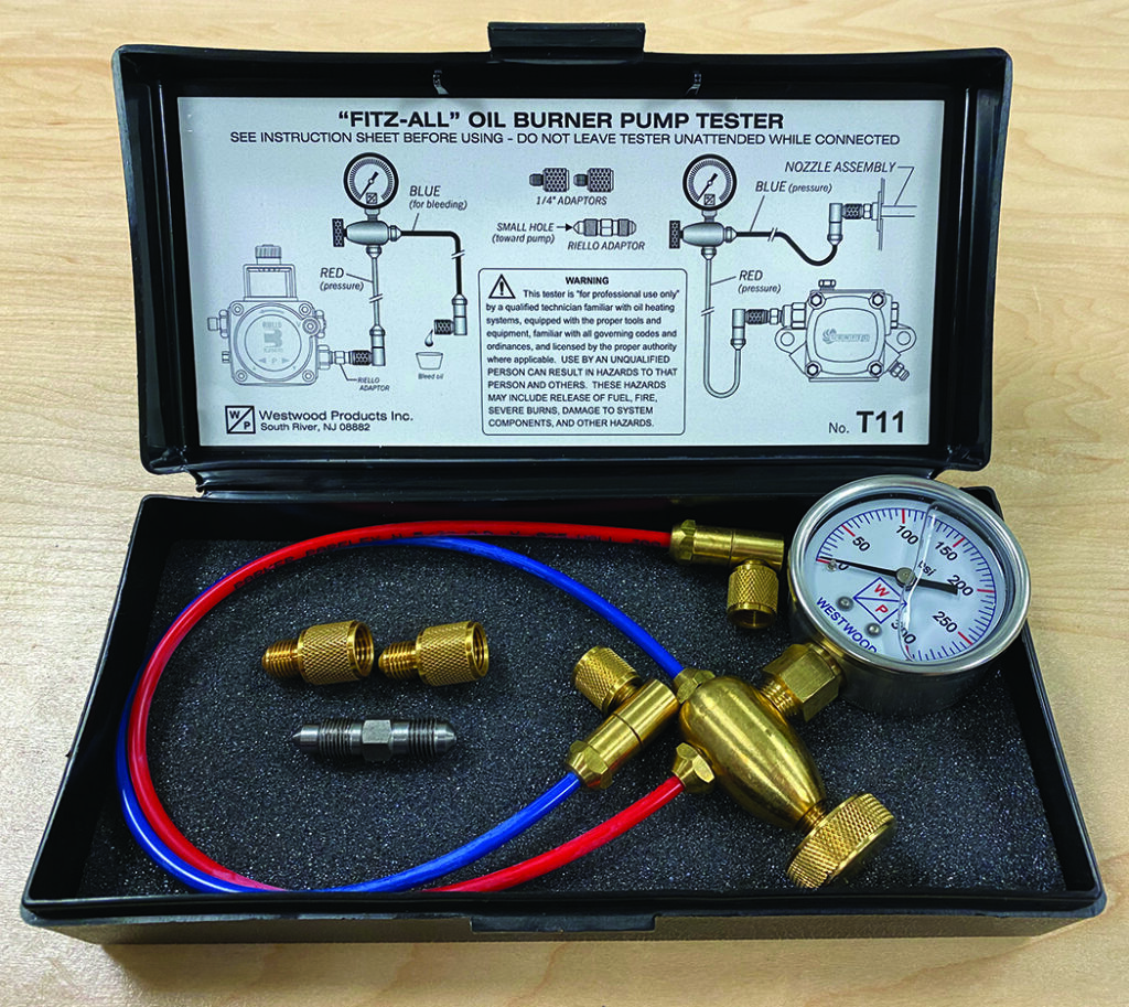
Figure 4
2. With a two-line system, your return line is considered an unmonitored line and if there’s a leak, it will not cause a lock-out condition and likely not be discovered until the homeowner is selling the home and a soil sample is taken.
3. With a two-line system, the oil in the return line is warmer than when it came in through the supply line, and once it’s outside, can create condensation that makes its way back to the oil tank. This promotes sludge caused by bacteria that grow in fuel oil.
4. With a two-line system, water in the tank could potentially freeze, block the return line and cause the seal in the fuel unit to rupture.
5. With a two-line system, the return line increases the contact time with yellow medals that increases degradation of the product and surrounding materials (I got that one from my good friend Robert C. O’Brien).
Deaerators not only overcome the cavitation issue, but eliminate the concerns that come with having a return line. ICM
Alan Mercurio, Lead Technical Trainer & Assistant Director PPATEC, a division of the Pennsylvania Petroleum Association. Email: amercurio@papetroleum.org; phone: 717-939-1781 ext. 101 or on PPATEC’s Facebook Page.
“Do it Once. Do it Right.” is one of my favorite sayings from our friends at Taco Comfort Solutions. It’s something all technicians and installers try to live up to when servicing customers. I’d like to share some information on how troubleshooting and installing Taco’s 007e and 0018e has been made easier with Taco’s innovative technology. See Figure 1.
Taco’s 007e Circulator
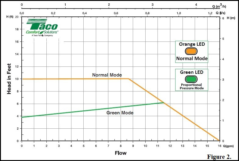
Let’s start with the circulators and questions you might have, such as what do the solid and flashing lights mean? The Taco 007e® is a variable speed, high-efficiency wet rotor circulator with 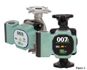 an ECM motor. For installations, the 007e performance is ideal for hydronic zoning to reduce velocity noise or banging of zone valves closing against high head pressure circulators. Remember when we used to remove one of the springs from an older style zone valve to prevent this from happening? No need to worry about that anymore because the 007e has an additional Green Mode operating curve that will self-adjust automatically. How cool is that? This circulator also reduces power consumption by up to 85% compared to equivalent AC permanent split capacitor circulators.
Here’s how it works—the circulator will start in what’s called the normal mode; you’ll see the Orange LED during this mode. After seven days of constant running, the 007e will adjust its curve to Low Proportional Pressure curve for power optimization. This is the Green Mode; the Green LED will be displayed during this period. The 007e will reset to the original normal mode curve every time it cycles OFF. See Figure 2.
Now for some troubleshooting; if you encounter a White LED flashing on the circulator, this is an indication that the system is air-bound and you’ll need to purge the system. Believe it or not, this circulator is capable of attempting to self-purge itself. Here’s how—if the circulator becomes air-bound, it drops itself down to seven watts of power, and then quickly jumps up 42 watts, in most case this will burp the air out of the circulator and hopefully get caught and removed by your air eliminator in the system. If you encounter a solid Red LED, this indicates that there’s a blocked rotor and the circulator was not able to dislodge whatever is causing the blockage.
If anything impedes the flow of the impeller, the circulator recognizes this and will go to its flashing Red & White mode, drops itself down to its lowest power, then returns to full power, and proceeds to spin the impeller forward-and-backwards to cause a vibration that attempts to dislodge the blockage. Once the blockage is dislodged, the circulator will resume its normal operation. If it’s not able to dislodge the blockage, the circulator makes 100 attempts to restart (that process lasts approximately 15 minutes). Every restart is signaled by a short White flash of the LED light. If the locking is not removed through the automatic release process after 100 attempts to restart the circulator, it goes into standby and the LED remains a solid Red.
In this case, follow the manual procedure: during any attempt, the Red LED light keeps blinking; after that the circulator tries again to start. If the locking is not removed through the automatic release process (the warning light returns to Red), perform these manual steps to unlock the circulator:
1. Disconnect power to the circulator.
2. Close both isolating valves and allow cooling. If there are no isolation valves, drain the system so that the fluid level is beneath that of the circulator. This would also be a good time to consider installing isolation valves.
3. Loosen the four motor bolts and remove the motor from casing. Carefully pull the rotor/impeller from the motor.
4. Remove impurities and deposits from the impeller and casing. Then reinsert the rotor/impeller into the motor, restore the power and check to see that impeller is rotating freely.
If the circulator still doesn’t run it will need to be replaced.
Taco’s 0018e Circulator
The Taco 0018e circulator is awesome; it features Bluetooth technology and is a versatile, variable speed, high-efficiency wet rotor circulator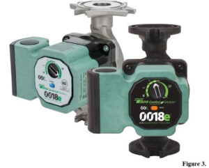 with an ECM motor. It’s ideal for closed loop hydronic heating, open loop or domestic water applications. If you download the Taco 0018e Mobile App, you can see and control real-time system performance, as well as run system operation and validation reports, including performance diagnostics and history. You’ll know the most efficient setting based on real-time feedback and alleviate the problems of over-pumping.
You can now design systems with precision. See Figure 3.
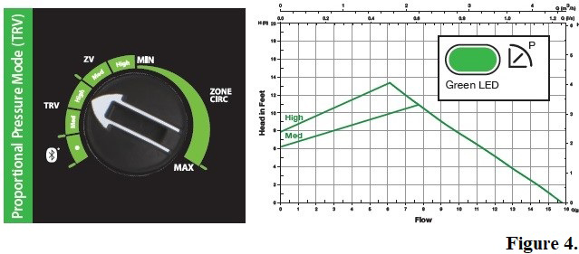
Once you’ve downloaded the App to your device (phone or iPad), you can adjust the performance curves with accuracy. For a panel radiator with this circulator’s variable speed capabilities, you can set it up for a proportional pressure mode, so the circulator maintains a proportional pressure differential as the heating load increases or decreases. Your selection options here are Medium and High. See Figure 4.
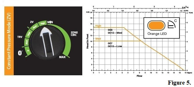
A system with zone valves can be placed in the constant pressure mode. In this mode, the circulator will maintain a constant pressure differential in the system as the heating load increases or decreases. Once again, your selection options here will also be Medium and High. See Figure 5 for the equivalent 00 model at each setting.
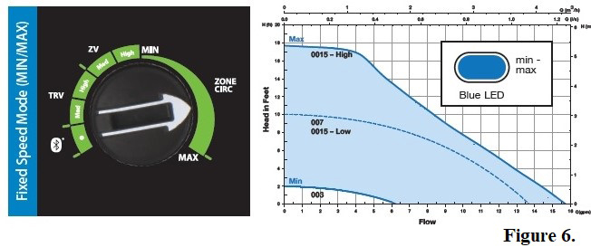
Finally, a system zone circulator can be placed in the fixed speed mode, where the circulator will be infinitely adjustable and operate between its minimum and maximum speed. This allows you to control the circulator’s flow rate to precisely match the design load conditions. See Figure 6 for the equivalent 00 model at each variable speed setting.
Note: As far as the troubleshooting goes with this circulator, all steps pertaining to the 007e as relates to the Red & White lights applies to this circulator as well.
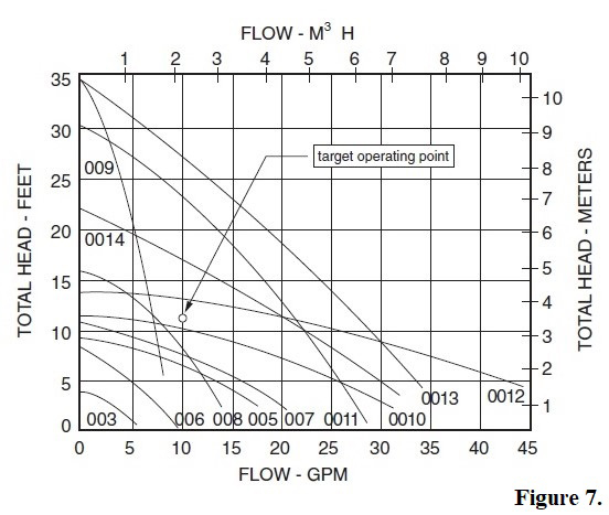
Service Education Circulator Troubleshooting Circulators These are just two of the many circulators available and happen to be favorites of mine. There are many others, both in type and brand, and choosing the right circulator is something many—including myself—have not taken into consideration over the years. Guilty as charged. Let’s be honest—how many of us believed for years that the Taco 007e was the right circulator for just about any scenario? Just because it worked and was heating the home doesn’t mean it was the right application, nor was it likely providing the optimum performance and comfort that our customers deserved. This is why it’s important to size a circulator using the chart provided by the circulator manufacturers. See Figure 7. ICM
Alan Mercurio is the Lead Technical Trainer & Assistant Director at PPATEC, a division of the Pennsylvania Petroleum Association. He can be reached by email: amercurio@papetroleum.org; phone: 717-939-1781
ext. 101 or on PPATEC’s Facebook Page.
In ICM’s July/August issue, I mentioned how I looked forward to writing about the Carlin Pro-X 70200 Primary Control. The diagnostic capabilities of this control, as my friend Michael Warn of Carlin/Hydrolevel would say, provide you with a roadmap to determine what component to check as well as what caused that component to fail. Let’s use an example of the control showing a fault code that says “Check Motor” “High Amps” (Figure 1).

Notice it does not say replace motor; it is just pointing you in a direction that will likely lead to solving the issue(s) in a more efficient way. If you see that message, make sure the power is off to the appliance, then flip the igniter back (open) to expose the burner’s blower wheel. Push it forward to see if it feels tight/sluggish. Then remove the motor from the burner housing and turn the burner’s blower wheel again. If it moves with ease, then I would suspect it was the fuel unit binding up, and likely is in need of replacement. You can confirm this by using the burner coupling to turn the shaft on the fuel unit, and confirm it is in fact binding up.
If the burner blower wheel is hard to turn after removal, then it is the motor that needs replacement. However, still check the fuel unit. For this scenario, let’s pretend it is the fuel unit. Although we know it will be replaced, there are still some diligent steps we need to take in the hopes of preventing a call-back.
The 5 Whys
In my workshops, I often talk about cause, effects and chain of events. In the National Oilheat Research Alliance’s (NORA) Oilheat Technicians Manual–Silver, we refer to this as asking the 5 Whys. It is great that we have determined what part needs to be replaced, but we need to ask ourselves what caused it to fail in the first place? In this case, check for water in the fuel and the condition of the fuel filter and strainer. You’d more than likely replace those at this time and also check the system vacuum. All of these steps don’t really take that long, and they will most likely lead us to what actually caused the fuel unit to fail.
To check the system vacuum, you first need to know the anticipated vacuum. To determine that, just remember 1′ of vertical lift = 1″ vacuum and 10′ of horizontal run = 1″ vacuum. Then add any filters, fittings and valves. If the vacuum is lower than your anticipated vacuum, you have a leak somewhere and this needs to be fixed. If your vacuum is higher than your anticipated vacuum, you have a restriction somewhere and that needs to be corrected.
Further testing
Another fault code, in this case from the Beckett GeniSys via the contractor tool (Figure 2), shows the message “DID NOT LIGHT.” This could be something as simple as the electrodes are out of alignment, which you could check with an electrode gauge; it could also be a faulty igniter. There are a couple of ways to check this. One way to test the igniter is the secondary coil test—place an ohmmeter across the igniter output terminals with the power off and measure the resistance between both springs/clips. The reading should be less than 2,000 Ohms and should equal the reading you get from both spring/clip to ground reading +/- 10%

Then measure the resistance from each igniter post to ground (Figure 3). The igniter is considered good if the resistance from each post to ground has no more than a 10% difference between posts.

Each manufacturer is different and they should be consulted for the proper output range and differential. It’s also important that you verify continuity between the igniter case ground and true ground.
Another test that is approved by most manufacturers is to bring the igniter output terminals to within ½ to ¾ of an inch apart and turn on the power (Figure 4). A strong, blue spark should be generated. Let it spark for about five minutes to see if the spark changes from blue to orange; if it does, replace the igniter.

Finally, you could also test the igniter with what is referred to as the input current test. Bring the igniter output terminals to within ½ to ¾ of an inch apart, as described earlier. Then using a multi-meter capable of reading milliamps, put it in series with the hot line going to the igniter and turn it on (Figure 5). Again, the reading should stay steady and not vary for at least five minutes with a strong blue spark throughout the test, while staying within 10% of the rated amperage draw for the device.

If you have any questions as to how to check and test any of the items referred to in this article, you can find the information in NORA’s Oilheat Technicians Manual – Silver, or feel free to E-mail me. ICM

Alan Mercurio is the Lead Technical Trainer & Assistant Director at PPATEC, a division of the Pennsylvania Petroleum Association. He can be reached at amercurio@papetroleume.org, 717-939-1781 ext. 101, or on PPATEC’s Facebook Page.
As I make my way back onto the pages of ICM (it’s been a while), I’d like to share a few of my thoughts and observations about how far our industry has advanced over the past several decades, and where it’s headed with today’s technology. I chose the title of this article because I want to talk to you about just that—change and acceptance. In future articles, I will go deeper into various systems and components, how they work and how to troubleshoot them.
Change – Many of us are often reluctant to change. The longer we’ve been in the industry, the harder it seems for some of us to keep up with those changes. My hope is that through this series of articles you’ll embrace these changes. If you have already, I hope you’ll be patient with those who haven’t and guide them by sharing what you’ve learned and the benefits to both you and your consumer, our customers.
Acceptance – Naturally, acceptance is the key to embracing change with anything in life. When we take the time to learn about any new system and/or component—this makes embracing that much easier, even for us stubborn industry veterans. I’ve been in the HVAC industry for 30+ years, and although I’m an advocate of advanced technology and improving things whenever and wherever we can, some of the changes have taken me outside of my comfort zone over the years.
Fortunately, I learned early in life that as long as you keep an open heart and an open mind, you can learn just about anything. As in industry instructor, I often share this advice with my students and I have witnessed it help both them and me embrace changes.
Technology in Today’s Industry – As I sit here sipping my coffee and writing this article, I think about how I can reach for my phone and in a couple of swipes on the screen, I can see in real-time how much oil is in the tank at the PPATEC HVAC training facility in Harrisburg, PA through the Beckett Link App. I can also monitor and even do some basic troubleshooting of the Regal furnace in the lab, through a Cloud-based application provided by NRGmax. These two examples are just the tip of the iceberg in terms of how many innovative and advanced controls we have today in our industry.
Readily available information – When I’m teaching classes or working in the lab with my fellow technicians, I often find myself telling them they’ve got it made today when it comes to troubleshooting equipment and components. I talk about the processes we followed back in the day to diagnose a system, and how with today’s advanced technology, many of those steps have been removed, making a techs’ ability to diagnose a system easier and less time-consuming. How, years ago, most of my technical troubleshooting guides and manufacturer’s installation and operation manuals were stored in a milk crate that was between the seats in my service van. By the time I was a senior tech, I had graduated to having two milk crates. It’s not about keeping everything you need to know in your head, but knowing where to find the information when you need it.
Today, you can have an unlimited amount of milk crates filled with valuable information, they just don’t have to be kept in you service van anymore; they are kept in folders on you Smart phones or other devices.
Trevor Brubaker, a fellow technical instructor, has the Evernote App on his Smart phone. It’s designed for note taking, organizing, task management and archiving data, such as technical notes, which can be quickly found just by using its keyword search function.
Among the advanced controls I look forward to writing in a future article is the Carlin Pro- X 70200 Primary Control. Michael Warn is a technical support specialist and fellow instructor who works for Carlin/Hydrolevel. He describes the troubleshooting feature of this control as not necessarily telling you what component needs to be replaced, just providing a roadmap of components you should check, and then determining what caused that component to fail.
In the next issue, I’ll take a deeper dive into this control, how it works and how to utilize its diagnostic fault history capabilities and control settings. I’ll also include a deep dive into the Beckett GeniSys.
Another quote I’m fond of sharing with my fellow techs and students is, “Once you understand the sequence of operation, troubleshooting is nothing more than the process of elimination.”
I look forward to sharing things I have leaned and continue to learn, and I thank my friends at ICM for providing me with this platform to share technically-relevant articles over the next six months. ICM