If you have been in this business for even just a few years, you’ve probably heard the expression, “Heat goes to cold.” If you were to ask someone, “Where does heat go?” they would say heat rises…but that’s not necessarily true. Hot air rises, but heat goes to cold… always.
Mother Nature hates an imbalance and whenever it exists, she does everything in her power to equalize or balance it. When your heating system delivers warmth to your house, it eventually leaves through the windows, roof and siding. Why does the heat leave? There is an imbalance between the temperature inside the house and the temperature outside. Heat goes to cold… always!
The same thing happens in the Summertime. When it is very hot outside and your house is cooler inside, the heat outside wants to go to the cooler indoor temperature. How do we typically make the indoor cooler? Most people would say the air conditioner makes the house cool, which is true, but how it does so eludes most people. We use an air conditioning system that removes heat from the indoors and sends it outside. That’s because you can’t make cold. Instead, to create a cooler atmosphere, you have to remove the heat, which is the basics of refrigeration. Whenever you feel cold, it is caused by a lack of heat.

Therefore, if we know that heat wants to go to cold, why is a “heat pump” called a heat pump? Why do we have to pump the heat when heat normally goes to cold? The reason is a heat pump, rather than creating heat, it simply moves heat. For example, a heat pump can move thermal energy from the cooler outdoor air into the warmer inside room. It pushes heat in a direction counter to its normal flow (cold to hot rather than hot to cold), hence, the word pump. A boiler or furnace burns fossil fuel to create heat. A heat pump simply uses an existing source of renewable energy like the heat that exists in the outdoor air. This can lead to reduced consumption of energy while at the same time providing comfort.
The definition of refrigeration is the process in which work is done to move heat from one location to another. It may also be defined as lowering the temperature of an enclosed space by removing heat from that space and transferring it elsewhere. Refrigeration uses refrigerant to move the heat as it changes state. For several years now, R410A has been the refrigerant used in the heat pump industry. However, that is about to change to new refrigerant called R32 that will be introduced by the end of 2024 (more on refrigerant changes in the next issue).
The properties of 410A allow the refrigerant to be a liquid well below freezing. It has a freezing point at -155°C (-247°F). It has a boiling point of -48.5°C (-55°F). As a liquid refrigerant, when it evaporates into a vapor, it is absorbing heat. When the refrigerant is in its vapor state, containing all that energy, and then condenses back into a liquid, it rejects or expels the heat it originally absorbed. That phase change contains a significant amount of energy.
For example, when you change the temperature of 1lb of water from 211°F to 212°F, it requires one BTU. When you change 1lb of 212°F water to 212°F vapor (steam), it takes 970 BTUs, which you “get back” when the vapor condenses back to its liquid state.
A heat pump incorporates the vapor-compression refrigeration cycle to move heat either away from an area where it’s not wanted (cooling) or move heat into a space that needs it (heating). Due to the unique operating properties of R410A, an Air-to-Water or Air-to-Air heat pump has the ability to take heat (energy) out of the air that we would view as very cold but to the refrigerant is warm. This applies to the heating mode of the heat pump.
The cooling operation is identical to that of an air conditioner. Again, using refrigerant and the vapor-compression cycle, the cold liquid refrigerant flows through the air conditioning coil as room air blows across it. The heat from the air goes to the cold liquid refrigerant, thus leaving the air cooler than it was when it entered the coil. The absorbed heat “flashed” the cold liquid refrigerant into cool vapor, which then flows outside to the compressor. There, the cool vapor will be compressed (by the compressor) into a high temperature vapor.
The vapor, which is storing a lot of energy (the heat from the home we wanted to remove), is pumped through a condensing coil where a fan is blowing outside air across it. This outdoor air is hot relative to our comfort but much cooler than the temperature of the hot vapor refrigerant. The hot vapor tranfers its energy/heat to the outside air thus completing the process of removing heat from the house and condenses back into a warm liquid.
Reversing Valve
Heat pumps have the unique ability to either heat or cool a home through a simple device called a reversing valve. There are four key components required: an evaporator, a condensor, a compressor and an expansion valve. By adding the reversing valve, the heat pump can “reverse” the role of these key components and be able to provide heating or cooling from the same compressor.
Coefficient of Performance (COP)
Another term unique to heat pumps is Coefficient of Performance (COP). This term expresses how efficient the heat pump is with regards to the amount of energy it uses relative to the amount of energy it delivers.
The term was developed to compare heat pump systems according to their energy efficiency. A higher value implies a higher efficiency between the pump’s consumption of energy and its output. Design conditions will impact the heat pump’s COP performance factor. Air-to-Air and Air-to-Water heat pumps have, in the past, been negatively impacted in their performance by colder outdoor temperatures. However, with the advances in compressor technology, specifically invertor-driven compressors, these Air-to-Air and Air-to-Water heat pumps are capable of extracting energy (heat) from very cold outdoor temperatures and transferring to the energy to the heating medium (water or air). ICM
If you have any questions or comments, e-mail gcarey@fiainc.com, call (800) 423-7187 or follow me on Twitter at @Ask_Gcarey.

Electricity is the lifeblood of modern heating and cooling systems, powering a vast array of devices and technologies that maintain comfortable indoor environments in homes and businesses around the world. Adding to our previous discussion about how energy is produced, in Part 2 we will explore how electricity is utilized in these systems, the components involved and the ongoing advancements aimed at enhancing their energy efficiency and possibly reducing their environmental impact.
The Fundamental Role of Electricity in HVAC Systems
Heating, Ventilation & Air Conditioning (HVAC) systems are complex networks of mechanical and electrical components that control temperature, humidity and air purity within indoor spaces. The primary roles of electricity in these systems include:
1. Driving Motors & Compressors: Electric motors are essential for running the fans and compressors that circulate air and refrigerant through the system. Compressors, which are powered by these motors, play a critical role in the refrigeration cycle by increasing the pressure and temperature of the refrigerant to help increase the amount of available heat exchange.
2. Heating Elements: In electric heaters, electricity is used to generate heat directly through resistance heating elements. As electric current flows through these elements, its resistance converts the electrical energy into heat, which is then transferred into the air.
3. Control Systems: Electricity powers the control systems that operate HVAC units, including thermostats, sensors and user interfaces. These components work together to monitor and regulate the indoor climate based on user settings and environmental conditions.
4. Safety & Diagnostics: Electrical systems also power various safety devices that protect the HVAC system from overheating, electrical overload or failure. Diagnostic tools powered by electricity help in monitoring system performance and troubleshooting equipment and operational faults.

Enhancing Energy Efficiency
With HVAC systems being significant consumers of energy, there is a strong emphasis on improving their energy efficiency to reduce electricity usage and operational costs. Several technologies and strategies have been developed to achieve this:
• Variable Frequency Drives (VFDs): These devices adjust the speed of electric motors based on the real-time demand of the HVAC system. By operating at variable speeds, VFDs reduce the amount of electricity consumed compared to motors running at full speed continuously. These VFDs are commonly applied to motors that operate fans, etc.
• Smart Thermostats: These advanced thermostats optimize HVAC operations based on learned behaviors and real-time data. They can adjust temperatures according to usage patterns, weather conditions and the number of occupants, significantly reducing unnecessary energy consumption.
• High-Efficiency Systems: Newer HVAC models are designed to use electricity more efficiently without sacrificing performance. This includes improvements in the design of compressors, heat exchangers and fans, as well as the use of better insulation materials and more efficient electrical components.
Integration with Renewable Energy
The environmental impact of traditional HVAC systems, especially those dependent on fossil-fueled electricity, has prompted a shift towards integrating HVAC systems with renewable energy sources, including:
• Solar Powered HVAC: These systems use solar panels to convert sunlight into electrical energy, which can either be used directly by the HVAC system or stored in batteries for later use. This not only reduces reliance on the grid but also decreases the carbon footprint of the building.
• Hybrid Systems: Some advanced HVAC systems can switch between electricity and renewable energy sources depending on availability, further enhancing energy efficiency and sustainability.
Future Technologies & Innovations
The future of HVAC systems is focused on further reducing electricity consumption while improving indoor air quality and system reliability. Emerging technologies include:
• Internet of Things (IoT): IoT-enabled HVAC systems can connect with other smart devices and systems, allowing for greater automation and efficiency. These systems can autonomously adjust settings based on real-time energy costs, weather forecasts and occupancy sensors.
• Phase Change Materials (PCMs): Used in HVAC systems, PCMs can store and release heat or cooling energy, which reduces the need for continuous operation of compressors and electric heating elements during peak times.
• Geothermal Heat Pumps: Utilizing the stable underground temperature, geothermal systems offer an efficient alternative for heating and cooling by circulating a fluid through underground pipes, significantly reducing electricity use.
• Advanced Insulation Techniques: Enhancing the insulation of buildings reduces the workload on HVAC systems, thereby decreasing the energy required for maintaining comfortable indoor temperatures.
In conclusion, electricity not only powers the essential functions of HVAC systems, but also drives innovations that improve their efficiency and environmental sustainability. As the world moves towards more renewable sources of energy and advanced technologies, the role of electricity in heating and cooling systems will continue to evolve, aiming for optimal performance with minimal environmental impact.
This ongoing evolution promises not only significant cost savings for consumers but also a substantial reduction in global energy consumption and greenhouse gas emissions.
If you have any questions or comments, e-mail me at gcarey@fiainc.com, call me at (800) 423-7187 or follow me on Twitter at @Ask_Gcarey. ICM
With the current emphasis on electrification coming at us from all directions, including local, State and Federal agencies, there is a lot of talk about electrifying everything. That has me thinking a lot about electricity—what, actually, is it? How is electricity produced?
Like water and air, most people tend to take electricity for granted. However, when you stop and think about it, we use electricity to do many jobs every day—from lighting, heating and cooling homes to maintaining daily hygiene to powering televisions, computers and cell phones. Imagine what life would be like without it.
Electricity is a form of energy: the flow of electrons. If we take a walk down memory lane to high school science class, we learned that all matter is made up of atoms, and the center of an atom is called a nucleus. The nucleus contains positively charged particles called protons and uncharged particles called neutrons. Surrounding the nucleus are negatively charged particles called electrons. The negative charge of the electron is equal to the positive charge of the proton, and number of each is usually the same. When this balance between protons and neutrons is upset by an outside force, the atom may gain or lose an electron. When electrons are “lost”, the free movement of these electrons makes up an electric current.
Lightning, for example, is a form of electricity; it occurs when electrons move from one cloud to another or jump from a cloud to the ground. Have you ever experienced a shock when you touch an object after walking across the carpet? That “static electricity” is caused when a stream of electrons transfers from that object
to you.
Electricity is part of nature and one of the most widely used forms of energy. Considered a secondary energy source, electricity comes from the conversion of other sources of energy, such as natural gas, nuclear power, coal, oil and other natural sources called primary sources. This is why, many years ago, towns and cities were built along waterfalls (a primary source of mechanical energy) that used waterwheels to convert the falling water into useful power.
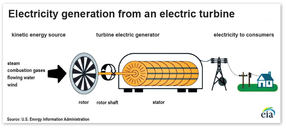
How is electricity generated?
An electric generator converts mechanical energy into electrical energy. It is based upon the relationship between magnetism and electricity. When a wire (which can conduct electricity) moves across a magnetic field, an electric current occurs on the wire. The electric utilities have large generators with a stationary conductor. A magnet is attached to the end of a rotating shaft, located inside the conductor, which is wrapped with a long, continuous piece of wire. As the magnet rotates, it induces an electric current in each section of the wire. All these small currents add up to one current of considerable size—which is used for electric power.
The electric utility power stations either use turbines, engines, water wheels or similar machines to drive an electric generator that can convert the mechanical energy to electricity. Steam turbines, water turbines, gas combustion turbines and wind turbines are the common methods used to generate electricity.
Most of the electricity in the U.S. is produced using steam turbines. The turbine converts kinetic energy of fluid moving (liquid or gas) to mechanical energy.
Different types of turbines
1. Fossil-fueled steam turbines: Fuel (such as coal, oil and natural gas) burns in a boiler or furnace, heating water to produce steam. The steam, in turn, pushes on the blades of the turbine.
2. Natural gas: When burned, natural gas produces hot combustion gases that pass directly through a turbine, spinning the blades to generate electricity.
3. Nuclear power: In a nuclear plant, a reactor contains nuclear fuel (typically enriched uranium). When the atoms of uranium are hit by neutrons, they fission (split), releasing heat and more neutrons; those neutrons then strike other uranium atoms, releasing even more heat. This continuous process of nuclear fission releases a tremendous amount of heat, which then turns water into a steam that spins a turbine, generating electricity.
4. Hydropower: In this process, flowing water (either from reservoirs created by dams or free-flowing rivers) is used to apply pressure to the turbine blades to spin the generator, producing electricity.
5. Solar power: Derived from the energy of the sun, this process is called photovoltaic conversion. Electricity is generated directly from the light of the sun in a photovoltaic (solar) cell. Solar-thermal electric generators use the radiant energy from the sun to produce steam to drive turbines
6. Wind power: Energy contained in the wind is converted into electricity. As the wind blows, it turns the blades of the wind turbine, generating electricity.
These last four turbines—sometimes categorized as “renewable energy sources”—do not rely on fossil fuels to spin the turbine blades of the electric generator.
The electricity produced by the generator travels along cables to a transformer, which changes the electricity from low voltage to high voltage. The reason for this is that electricity can be moved long distances more efficiently using the high voltage. The transmission lines are used to carry the electricity to a substation, where transformers change the high-voltage electricity back into lower-voltage electricity. From the substation, distribution lines carry electricity to homes, offices and factories which require the low-voltage electricity.
Electricity is measured in units of power called watts, in honor of James Watt who invented the steam engine. One watt would be considered a very small amount of power. A kilowatt represents 1,000 watts. A kilowatt-hour (kWh) is equal to the energy of 1,000 watts working for one hour. The amount of electricity a power plant generates, or a customer uses over a period of time, is measured in kilowatt-hours (kWh).
In Part 2, we will discuss how electricity works, the terminology associated with electrical circuits and the wiring strategies used to deliver this “invisible energy” throughout a structure.
If you have any questions or comments, e-mail me at gcarey@fiainc.com, call me at (800) 423-7187 or follow me on X at @Ask_Gcarey. ICM
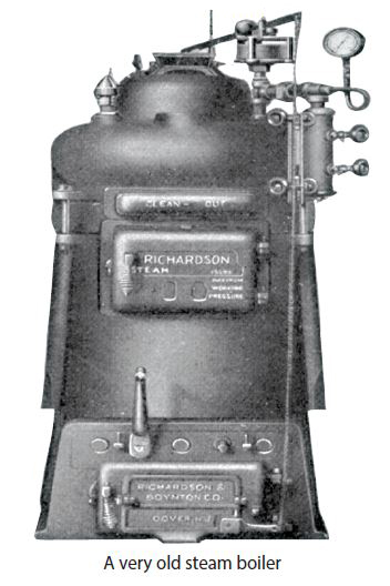
Pumping Away: And Other Really Cool Piping Options for Hydronic Systems is the title of a book that Dan Holohan published 30 years ago.
I can’t believe it has been that long since the book was first published. I think Pumping Away accomplished two important things. Holohan’s book educated the hydronics industry about why pump location is so important, as well as the benefits it provides to a hot water system when implemented correctly. However, I also believe that Holohan wanted to recognize Gil Carlson, who published a technical paper on this very subject. Carlson worked at Bell & Gossett, where he developed various theories and applications that today we consider standard design procedures. His most popular paper was titled the “Point of No Pressure Change,” and covered the importance of proper pump location in a closed hydronic system.
What is meant by the proper location of a circulator in a closed system? The circulators in the system should be located so they are “pumping away” from the expansion tank. When installed in this manner, once the circulator turns on, the pressure differential it develops will be added to the system’s static pressure. The static pressure is the pressure that exists throughout the system when the circulator is off—simply the weight of water. If you were to place a gauge at the bottom of a column of water 28″ high, the gauge would register one psi. That is one pound of pressure per square inch.
When centrifugal pumps are used in closed, pressurized hydronic systems, they are referred to as circulators; the pump is not pushing or pulling the water around the system but rather it is circulating the water through the system. The circulator does not create pressure, only pressure differential. In addition, the pressure on the discharge side of the circulator has to be higher than the pressure found on its inlet side.
Remember the old saying, “high pressure goes to low pressure?” In a hydronic system, think of it this way: The system is a closed, pressurized wheel. When the circulator is off, the water does not circulate through the wheel. However, when the circulator turns on, it upsets the balance that existed. The direction the water flows is determined by the higher pressure found on the discharge side of the circulator. The key difference between pressure and pressure differential is that when the circulator turns on, it does not matter if its discharge pressure increases or if its suction pressure drops, as long as the pressure on the discharge side of the circulator is higher than the pressure on its suction side. Since there is a difference in pressure across the circulator, the water in the system circulates. In fact, all the water in the piping circuit moves instantly. That is because water is not compressible, so when the circulator comes on and upsets the balance that existed in the circuit, all the water circulates.
Therefore, if the water in this closed hydronic system is going to circulate regardless of whether the circulator is on the supply or return, why all the fuss about its location? The answer has to do with how the circulator can change the system’s static pressure. If the circulator is located on the supply, pumping away from the expansion tank, the system’s pressure will be increased. If the circulator is located on the return, pumping toward the expansion tank, the pressure in the system will be decreased.
This drop in pressure can cause all sorts of problems. When exposed to a lower pressure, air that is entrained in water will come out of solution in the form of bubbles. This can cause gurgling noises, a reduction in heat transfer efficiency and quite possibly air-binding of radiation, requiring a service call to purge the air. If the circulator’s pressure differential is high, it can drop the system’s pressure on the top floor into a vacuum. Of course, any float vents exposed to a vacuum will draw air into the system.
How big does that circulator need to be to cause this situation? It depends on each individual job, but typically, the type of circulators found in most commercial jobs, such as apartment buildings, office buildings and churches, could have one of these circulators.
Point of No Pressure Change
Why can’t the circulator change the system’s pressure at the point where the expansion tank connects to the system? This is a question asked often, both in the field and at our hydronic seminars. Boyle’s Law says that if you have a gas (air) trapped in a tank (expansion tank), its volume will shrink if you add pressure to it. Likewise, its volume will expand if the pressure is lowered. In other words, if you squeeze a gas, its pressure will rise; conversely, if you let the gas expand, its pressure will drop. How does all of this relate to hydronic systems?
To change the pressure in the expansion tank (diaphragm or steel), you have to squeeze the air that is in there. When the boiler heats the water in the system, the water expands, compressing the air in the expansion tank. This causes an increase in the system’s pressure, which can be seen on the gauge of the boiler. When you open the fill valve to add more water to the system, because the piping is already filled with water, the additional water enters into the expansion tank, compressing the air, causing a rise in system pressure that is indicated on the boiler’s gauge.
When a circulator turns on, does it change the volume of the water in that system? Or does it just circulate the water? Can you see the difference? If there is no change in volume of the water, then there is no change in the volume of air in the expansion, which means the pressure in the tank can’t change.
If the circulator is pumping away from the expansion tank, can it take water out of the tank? If you think Yes, where would you put it? The piping is already filled and you can’t compress water. If the circulator is pumping toward the expansion tank, can it put water into the tank? Air is compressible, so water can enter the tank. However, where would the water come from? If you think it could come from the piping circuit, then that means there would be a void in the piping circuit (and Mother Nature hates a void). No, when a circulator comes on, it can neither add nor remove water from the expansion tank. If the circulator can’t change the volume of the water in the tank, it can’t change the volume of the air (gas) in the tank, either. This means it can’t change the pressure in the tank or the piping connecting the tank to the system.
Every time a circulator turns on, it “looks” for this point. Depending upon whether it’s pumping away or towards the expansion tank, it either increases its discharge pressure or drops its suction pressure. This is why Carlson wrote his well renowned paper, to educate the engineering community on the “Point of No Pressure Change” and why Holohan wrote Pumping Away, to educate the hydronics industry about the benefits of locating circulators so they would be pumping away from the expansion tank.
Author’s note: Dan Holohan recently announced that he was retiring after 36 years of writing articles for our industry. I would like to congratulate Dan on a job well done. He has educated tens of thousands of people about steam and hot water heating systems. Dan also shared the life lessons he learned along his incredible journey and touched many of our lives, as well.
Twenty-four years ago, I was fortunate enough to have Dan convince the late Paul Geiger, former Editor of Oilheating Journal (now Indoor Comfort Marketing), to let me continue Dan’s Boiler Facts column. Thank you, Dan, and please enjoy your well deserved retirement with your family… especially with those grandchildren!
If you have any questions or comments, e-mail me at gcarey@fiainc.com, call me at (800) 423-7187 or follow me on Twitter at @Ask_Gcarey. ICM
As much as technicians may like the challenge of fixing a problem on an old steam system and bringing it back to its once majestic self, there are times when it makes sense to convert the steam system to a hot water system. Reasons could perhaps involve improved comfort and zoning capabilities for the homeowner, fewer headaches or a more efficiently operating heating system.
Let’s go through some steps to consider when converting from a steam system to a hot water system.
Assess the Existing Components
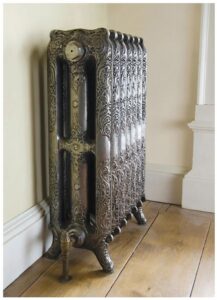
One of the first things to evaluate is the existing radiators. If dealing with radiators that are cast-iron column type with a wide space between each section, the conversion will not make sense. These column-style radiators were perfect for steam because they offered plenty of internal space, which allowed the steam to rise up while the condensate could easily slide down past it. However, because the sections are not connected with push nipples across the top, water is prevented from flowing effectively through each section.
If the radiators in the house are cast-iron tube style (with much thinner sections), there will be push nipples across the top of each sections. This will allow the water to flow throughout the sections and will work properly when converted to a hot water heating system.
Next, check whether the existing system utilizes one pipe or two pipes (obviously, the number of pipes connected to the radiator will determine the answer). If the system is one-pipe, it’s not practical to turn it into a hot water system; it can be done, but you will be drilling and tapping an outlet on the opposite side of each radiator for the return pipes. However, conversion to a hot water system will be possible with a two-pipe system. When inspecting a potential system for conversion, walk throughout the entire home or building and make sure all the radiators are piped for a two-pipe system.
Perform a Heat Loss Test
Performing an accurate heat loss inspection on the house is the next step before converting the system to hot water. Make sure to measure the square foot rating of Equivalent Direct Radiation (EDR) of all the radiators in the building; you want to ensure that when you convert the system to water, the amount of radiation will be sufficient to heat the house on the coldest days of the heating season.
For example, if the radiators are filled with steam at 1 psi, the steam temperature is 215ºF. Each square foot rating of that steam radiator could emit 240 BTU/H. When converted, the water temperature will only be 180ºF. Each square foot of radiation will emit 150 BTU/H. The question is, will there be enough radiation while circulating this lower temperature to keep the house warm? If the windows have been upgraded and insulation has been added to the structure—and if the original heat loss was perhaps exaggerated—the existing radiators should provide enough heat to keep the house warm.
Check for Leaks
Remember that a steam system operates at a typical pressure of no more than a couple of pounds. When converted to water, the static system pressure could be operating as high as 15–20 psi, which will surely reveal any leaks the system may have. If the steam boiler is still operable, crank the boiler pressure up to 10–12 psi and walk throughout the house, looking for any leaking steam or condensate. By doing this, you will have an idea of what needs to be addressed before the system is completely filled with water.
Evaluate the Piping
The next step is to completely remove each thermostatic radiator trap and replace it with an elbow and piping. Another option is to keep the traps, but take the covers off and remove the thermostatic element and, with a rag, wipe clean the seat of the trap. With the elements removed, the water will be able to flow through the radiator and into the return piping.
In some conversions, the steam piping is removed completely and re-piped with either copper or Pex piping. In other instances, the plan is to reuse the existing supply-and-return steam pipes.
A word of caution: the main return piping may be too small for the hot water system. When a steam system condenses back to condensate/water, the volume is very small, especially when a steam system condenses back to condensate/water, The returns from each radiator, which are typically ½” in size, will be able to handle the radiator flow rate; however, the main return line may have to increase to handle the flow from all the radiators.
The new hot water boiler should be piped as you would normally pipe hot water boilers. Also, plan on removing any of the “near boiler” piping from the old steam system. Make sure to include an air separator, pressure reducing valve, circulator(s) (if you are zoning the new hot water system) and an expansion tank.
When selecting the expansion/compression tank, be sure to account for the additional water the system will have from the cast iron radiators as well as the steam supply piping. Expansion tank sizing is all about the volume of water in the system, not the BTUs of the boiler.
After going through all of these steps to make sure the conversion will be successful, you can see why sometimes the heating contractor may suggest keeping the steam system!
If you have any questions or comments, e-mail me at gcarey@fiainc.com, call me at (800) 423-7187 or follow me on Twitter at @Ask_Gcarey. ICM
Everyone involved in the heating and cooling industry, especially in the Northeast, has experienced a rapid increase in the popularity of Air Source Heat Pumps (ASHP). Without getting into all the reasons why, one interesting takeaway is that, when you understand how an ASHP can take heat out of the air and “pump” it into a home even when the outdoor temperature is 10°F, you can apply that to troubleshooting a steam system. As the Fall season begins and thermostats start calling for heat, existing older steam systems that may have received a new steam boiler will turn on. Or perhaps some renovation took place in a newly purchased home and radiators were relocated or changed. Whatever the reason, when you are tasked with solving a no-heat or noisy, banging steam system, remember the following;
• A steam system is filled with air any time the system is off; if you want heat, you have to get rid of all the air before the steam can get in and heat the radiation.
• A steam system operates nothing like a water system; when manufactured in the boiler, the steam desperately wants to turn back into water and will whenever it touches something cooler than itself. If you don’t make enough, it will never reach the furthest radiators.
• Steam boilers today really aren’t capable of producing dry steam internally, which is why manufacturers insist that you pipe the boiler according to their installation manuals.
• Steam boilers today are very different from the old boilers we are replacing. While some of those differences are good, unfortunately there are several that are not and may make some want to quit their job if those differences aren’t being taken into account.
I have also been writing articles about Air to Water Heat Pumps; their compressors incorporate invertor technology which, in the compressor world, is state-of-the-art. The invertor basically allows the compressor to operate like a variable speed pump; the expansion valve can operate over a wide range of loads and with the continuing development of the refrigerants, ASHPs can extract heat from lower outdoor air temperatures than what they were previously capable of doing. However, at the end of the day, for heat pumps to work at all, it all comes down to the vapor compression refrigeration cycle.
What does this have to do with problematic steam systems? If you understand the vapor compression cycle and if you understand what a steam system is trying to accomplish, both systems have similar attributes. Here is what I mean:
To make steam, the boiler has to heat the water in the boiler up to the water’s boiling point. What is the boiling point? It depends on what pressure the system is operating under. When a steam system operates under higher pressure, the water’s boiling point is higher. Also, the temperature of the steam is hotter. When I say the boiler has to heat the water, there are two types of heat needed to make steam. Sensible heat is the type of heat that a thermometer can “sense.” For example, when the boiler is operating at 2 psig, the boiler has to provide enough sensible BTUs to heat the water to 219°F. The other heat is known as latent heat. This is the amount of energy (BTUs) that is required to change the water’s state from liquid to vapor. Why? Remember, we are dealing with a steam system. For it to work, you must change the water into vapor. Continuing with our example, the boiler would have to add an additional 966 BTUs of latent heat per pound of steam. That is five times greater than the amount of sensible BTUs that was needed to bring the water to a boil under 2 psig. When this 219°F steam travels out into the system and fills a radiator, it condenses back to water. The temperature of the water can be 219°F, but the radiator has received 966 BTUs that it uses to warm the room.
When any medium goes through a phase change, it will either absorb or release a tremendous amount of energy; that is the parallel I was drawing between the vapor compression cycle and steam systems. In the compression cycle, instead of water, refrigerant is used, which has many favorable characteristics for the refrigeration process. It can operate under extreme temperature conditions (relative to what we consider “normal”), and it can change state from a liquid refrigerant to a vapor and then condense back to liquid, all while absorbing and releasing energy (heat) to where it’s needed (heating application) or from where it is not wanted (air conditioning application). Of course, there is no boiler in the refrigeration cycle. Instead, an evaporator is used to help change the refrigerant’s phase and the compressor is used to increase the pressure on the vapor, which results in a high temperature gas. Before the vapor enters the compressor, it first flows across the evaporator as a cold liquid refrigerant. The volume and temperature of the cold liquid is controlled by an expansion valve. Outdoor air or some other substance (such as geothermal) flows across the other side of the evaporator. The cold liquid absorbs the heat from the outdoor air (or geothermal field) and changes its state into a low temperature vapor. To prevent damage to the compressor, it is critical that only vapor and not liquid enter the compressor. The low temperature vapor gets “compressed” into a high temperature gas that then flows across a heat exchanger. The cooler medium (return air from the ductwork or water from a hydronic system) flows across the other side of the exchanger. This cooler substance (air or water) absorbs the energy from the vapor, causing it to condense back to its liquid form. In the condensing process, a tremendous amount of energy is transferred.
When we take it back to our steam heating systems, the boiler is our evaporator and, to some extent, our compressor. Its job is to add enough sensible and latent BTUs so that the water is changed into steam (vapor). When the steam enters the radiator, its surface and surrounding air temperature is cooler than the vapor (steam), causing it to condense back to water (liquid). In doing so, it gives off a tremendous amount of energy (BTUs) to the space.
How does this analogy help solve or prevent steam system problems? Make sure the boiler is making good, dry steam; when it produces wet steam, the water in its liquid state “robs” the vapor of its latent BTUs. When this happens, the steam is condensing in the piping network and not where its needed… in the radiators!
• How do we make good dry steam? Make sure the new boiler is piped according to the manufacturer’s installation instructions.
• A bouncing water line in the boiler can also make wet steam. If the water is moving in the gauge glass, it’s an indicator that the water in the boiler is dirty. It needs to be skimmed to rid the boiler of any oils and debris that cause surface tension on the water, prohibiting the steam bubbles from making their way through the surface and out to the system.
• When a boiler is under-sized or under-fired, it can’t produce enough steam to fill all of the radiators. The condensor side of the system (the radiators) is bigger than the evaporator side (the boiler). It is imperative that when you replace a steam boiler, you go upstairs and measure the amount of radiation in the building then size the replacement boiler to the connected load.
Whenever you are dealing with a steam system, it is vital that the boiler is making dry steam. If it isn’t, don’t waste your time chasing other symptoms or complaints; always start with dry steam.
If you have any questions or comments, e-mail me at gcarey@fiainc.com, call me at (800) 423-7187, or follow me on X at @Ask_Gcarey. ICM
As the push for “electrification” continues in nearly all aspects of our lives (electric cars, stoves and heating/cooling systems), there should be a discussion on how to incorporate the (relatively) new technology with the existing technology—especially when it comes to heating homes in the Northeast. What do I mean by “new” technology? Utility companies have been pushing consumers to upgrade heating and cooling systems to heat pumps, typically by offering enticing rebate or incentive programs for customers to make the switch to the all-electric (or at least partial electric) heating and cooling system.
Heat pumps have been around for a long time. Historically they would have been listed in three categories:
• Air to Air Heat Pumps
• Water to Air Heat Pumps
• Water to Water Heat Pumps
Recently though, a fourth category has been gaining market share: the Air to Water heat pump. Similar to the Air to Air style, it takes heat from the ambient outdoor air. Instead of heating air, Air to Water heat pumps use a refrigerant-to-water-heat exchanger to heat the system water, which is then circulated through the closed-loop hydronic system.
Utility companies have made the Air Source Heat Pump (ASHP) technology their primary choice of heat pump technology available. Using air instead of geothermal energy eliminates the expenses associated with drilling a well field and installing the tubing (anywhere from $10,000–$30,000), consuming the necessary footprint to support the well field and the operating costs of pumping the well all year long. The air is, well, already there… right in your backyard surrounding the heat pump. This allows for a cleaner, less expensive installation for both the contractor and the homeowner.
However, like so many things in life, there is a trade-off when using air source heat pumps vs. geothermal heat pumps (which have more expensive upfront costs), especially during the heating season. In the colder, northern climates such as New England, New York and Pennsylvania, as the temperature drops, the ability of the refrigerant to extract heat from the air is reduced. The heating system’s capacity, as well as efficiency, decreases as it gets colder outside. Most of the current ASHP manufacturers offer “cold-climate” heat pumps that can certainly operate in colder outdoor temperatures than before, but their BTU output and COP (Coefficient of Performance) are still reduced compared their rated capacities at 47°F. This is where a hybrid system comes in.

When a customer wants to install an air source heat pump into an existing home because of utility rebates or reducing their carbon footprint, instead of throwing away the older heating system (such as a warm air furnace or hot water boiler), they should keep the “legacy” heating system. The customer can operate their new ASHP system for the summer months in the Cooling Mode, which will keep the house comfortable. When the Fall arrives and outdoor temperatures drop, they can run the heat pump in the heating mode and it will operate very efficiently. Even though the air temperatures feel cold, the refrigerant is able to extract heat from the air very efficiently with variable speed compressors that adjust its output based upon the load conditions. As the temperatures outside become extremely cold, the customer can disable the heat pump system (which is starting to operate inefficiently) and have their legacy heating system (boiler or furnace) turn on and keep the house comfortable. When the extremely cold temperatures dissipate, the legacy system can be turned off and the ASHP system will come back on to provide heat for the house for the remainder of the heating season.

Most utility companies actually offer a rebate incentive for this type of hybrid operation through a category called Integrated Controls that offers the consumer incentive money (some programs as high as $500 per control/max [three] per house). For the control to qualify, it must be able to operate the heat pump in both heating and cooling mode. It also has to be able to measure the outdoor temperature and, at a pre-determined temperature in the winter, turn the heat pump system off and turn on the legacy system to maintain space temperature. Of course, as the outdoor temperature climbs, the control has to turn the legacy system off and bring the heat pump back system back on seamlessly. The switch-over temperature is usually referred to as the balance point. This point becomes the outdoor temperature where the heat pump can’t provide enough BTUs and/or it does it at a higher cost than operating the legacy system. When the switch-over takes place, the integrated control must to be able to turn the heat pump system completely off and only operate the legacy system. Some of the Integrated Controls that have been approved for this type of control are heat pump thermostats with WiFi capabilities. Through a smart phone or tablet, the consumer can operate their heat pump and legacy system to control space temperatures in their home.
If you have any questions or comments, e-mail me at gcarey@fiainc.com, call me at (800) 423-7187, or follow me on Twitter at @Ask_Gcarey. ICM
With the current emphasis on electrification and decarbonization coming from local, State and Federal bureaucracies, there is a lot of talk about using heat pumps to displace fossil fuel appliances and low-efficiency standard AC condensers. Of course, heat pumps have been around for a long time in the HVAC industry. When discussing heat pumps, historically there have been three categories:
• Air-to-Air heat pumps
• Water-to-Air heat pumps
• Water-to-Water heat pumps
In general, heat pumps are devices that can convert low-temperature heat into higher-temperature heat. The low-temperature medium is referred to as the source. This is where the energy comes from to heat the building. The “source” can be the outdoor air or tubing buried in the ground. This is where the “free” heat comes from—the renewable energy source. The converted “higher temperature” energy is then released into the sink—the place that can absorb this energy. An example would be an air handler unit that is moving cooler return air across a coil (the heat exchanger) and delivering the warmer air into the living space.
Most are familiar with Air-to-Air heat pumps, especially the mini-split units. They extract heat from the outside air and are very common throughout our market. Air-to-Air heat pumps deliver the high-temperature heat through either a forced-air network of duct throughout a home, or individual cassettes mounted throughout various rooms in the house. This type of heat pump is classified as an air-source heat pump. There are other heat pumps that extract heat by using water that is circulated through tubing that is buried in the ground. The earth heats the water circulating through a “field” of tubing and this heat is then converted by the heat pump into a higher temperature medium. If it is air, they are known as Water-to-Air heat pumps and if the high-temperature medium is water, then they are referred to as Water-to-Water heat pumps.
There is one additional type of heat pump that is starting to gain attention in our industry called an Air-to-Water heat pump. This style is similar to wall-hung boilers and can produce water temperatures from around 85°F up to 130°F. Air-to-Water heat pumps do not burn fossil fuel, which is another reason they are gaining in popularity. This unit extracts heat from the ambient air outside the home and transfers it through refrigerant piping to a module. This module contains a refrigerant-to-water plate heat exchanger that heats water, which is then circulated through floor heating systems, fan coils and low-temperature radiators. Since it is a heat pump, the whole cycle can be reversed and provide chilled water (45°F) for cooling. Air-to-Water heat pumps have been gaining popularity in Europe for the last 10–15 years.
Why a Heat Pump?
Heat pumps are considered the most energy efficient, electrically-operated heating and cooling system on the market. These modern Air-to-Water heat pumps can deliver between 3–5kWh of usable heat for every 1kWh of electricity that it uses. This equates to a Coefficient of Performance (COP) of 3–5 or 300%–500% more efficient than typical electrical resistance heat. The heat pump uses the renewable energy source (air) and therefore has no localized CO2 emissions. The same system can be used for heating in the Winter and cooling in the Summer. Another benefit to this style of heat pump is that they use an inverter technology to operate the compressor and can vary the speed of the compressor to match the actual load that the system is currently experiencing. This can provide more comfort by matching the output to the load. Furthermore, cycle losses are reduced, which increases the compressor’s efficiency and reduces wear and tear on the compressor, thus extending its life cycle.
By using air instead of geothermal energy, one can eliminate the expenses associated with drilling a well field and installing the tubing (anywhere from $10,000–$30,000), consuming the necessary footprint to support the well field and the operating costs of pumping the well all year long.
Where Does the Heat Come From?
Generally speaking, the heat contained in the soil, ground water and air all started as solar energy. Basically, we are taking energy from the sun and using it to heat the water for the hydronic systems. During warmer weather, the ground and the air absorb this heat and, as the weather gets colder, some of this heat dissipates to the outside air. However, the heat absorbed into the soil can take a long time to transfer back to the atmosphere—so even in the middle of Winter, the soil temperature in the earth is much warmer than the outside air temperature. This condition generally favors water source heat pumps because their efficiency or thermal performance remains high due to the warmer-source water temperature, whereas an Air-to-Water heat pump’s output capacity drops as the outside air temperature gets very cold (0°F to 25°F). The manufacturers are continuing to try and improve the efficiency of the refrigerant cycle, enabling the units to extract heat from colder temperatures while maintaining their capacities.
How the Heat Pump Does What It Does
Refrigerant plays a major role in the successful transfer of energy from one place where it is available to another place that needs or wants it. The refrigerant is a chemical that has unique properties that allow it to absorb heat from low temperatures and transfer that energy to a medium operating at higher temperatures. For this to happen, the refrigerant has to change its state from liquid to vapor and then back to liquid—and in doing so, undergo some pressure changes.
This whole process can be referred to as the “Refrigeration Cycle” and is the starting point for the operation of all vapor-compression heat pumps. There are four components that play a major role in this cycle. Their respective names indicate their function and how they play their part in the process:
• Evaporator
• Compressor
• Condenser
• Thermal expansion valve
First, a cold liquid refrigerant enters into the evaporator. The pressure of this cold liquid 410A refrigerant is low, and there is a direct relationship between the pressure that the refrigerant is at and what its corresponding temperature is, so that the lower the pressure, the lower the refrigerant’s temperature. Additionally, the refrigerant’s pressure/temperature will adjust as the “source” (air) temperature changes. As it gets colder outside, the temperature of the liquid has to become colder so that it can absorb heat from the relatively cold air outside. The key is, as it absorbs heat from the air outside, the refrigerant evaporates or changes state into a vapor or gas. Its temperature is still low, but warmer than when it was a liquid. This step is important because the next component in the system is the compressor and since liquids aren’t compressible, if the refrigerant didn’t evaporate into a vapor, the liquid entering the compressor would severely damage it.
The compressor’s job is just as it sounds: it compresses the low-temperature vapor. This creates a large increase in both its pressure as well as its corresponding temperature as the refrigerant leaves the compressor. Another factor to consider is that the electrical energy used to compress the refrigerant by the compressor is added to the refrigerant. Now we have a high-temperature vapor that contains a lot of energy ready to be utilized.
This high-pressure, high-temperature vapor then enters the condenser, and the cooler return water from the hydronic system is pumped across the exchanger. The refrigerant, being hotter than the water, transfers its energy to the cooler water, elevating the water temperature going back out to the heating system. This transfer of energy causes the refrigerant to change its state and condense back to a high-pressure liquid.
The last step in this process is for the high-pressure/high-temperature liquid refrigerant to flow through an expansion valve (either thermal or electronic). The expansion valve controls the flow of the liquid refrigerant through its orifice, drastically reducing its pressure and thus its temperature so that the refrigerant is back to the cold temperature it was at the beginning of this process. As Air-to-Water Heat Pumps become more popular, they will find a place in the renewable energy industry.
If you have any questions or comments, e-mail me at gcarey@fiainc.com, call me at (800) 423-7187 or follow me on Twitter at @Ask_Gcarey. ICM
As this column is being written for publication, we have been experiencing a very strange Winter in the Northeast area with some fairly wild temperature swings. One weekend in February, it was -12°F in Gloucester, MA, on Saturday morning and by Sunday, the temperature had climbed to 45°F. All the while, heat is still required and heating systems need to operate to maintain certain indoor air temperatures regardless of the outdoor temperature.
One of those systems was an older steam system that experienced banging noises whenever the thermostat called for heat. It all started when the old boiler finally quit. The replacement boiler was considerably smaller physically and consequently held less water. This created the need to install a boiler feed tank, which acted as a reservoir for the new replacement boiler and helped prevent the boiler from shutting down due to low water conditions (or flooding the boiler if a water feeder is present). This occurred when the automatic feeder became overactive due to the lack of water in the replacement boiler. With the boiler feed tank, all the system surges took place in the receiver, allowing the boiler to maintain a steady water line. This by itself isn’t uncommon, but trying to install the new boiler feed unit into these older systems can be treacherous and expensive if you are not careful—especially considering that the original system was not intended to have a vented receiver attached to it.
This particular system was a two-pipe air vent system. Due to its age, these systems were installed when one-pipe steam would have been the popular method of heating. In fact, at the time, steam traps hadn’t yet been invented. The heat loss in large, old buildings was great, which called for extremely large radiators. It was also very common to bring in outside air to ventilate the building; this was accomplished with large indirect radiators located inside tin ductwork.
In one-pipe steam systems, the riser, which supplies the steam, also handles the condensate that forms in the radiation. There is a counter-flow action that takes place inside those pipes. For this reason, it was important to have the right size pipe to handle those large loads. If the pipe was too small, it would cause spitting radiator vents and water hammer. To prevent this, heating engineers had to use “sewer-like” pipe sizes and supply valves to handle the condensate that would form by these large radiators. Another option was to use a second pipe on the outlet side of the radiator to handle the condensate, thus eliminating the counter-flow problem. The system could be described as a one-pipe/ two-pipe system because each radiator still used a steam vent. However, engineers had to ensure that the return pipe drained down individually to a wet return. This was important because the water acted like a trap, preventing steam from passing into the return side of the other radiators. Once steam is allowed into the returns, all kinds of problems can occur (condensate being held up in the radiators, spitting radiator vents and water hammer)!
When you install a boiler feed unit, all the returns must drain into this receiver. The only way water can then enter the boiler is by activating the feed pump with a pump controller located on the boiler. Since this receiver can’t withstand any pressure, it is vented to the atmosphere. As a result, all of those former wet returns now have no backpressure from the boiler to offset the pressure from the supply side. Now the steam can reach down into those former wet returns and shove all that water back and forth in the piping, eventually showing up at the vent pipe, filling the boiler room with steam. Of course, in the process, the water hammer is incredibly loud.
The answer to this problem is to install F&T (float & thermostatic) traps at the base of each riser drip and at the end of each main, as well as radiator traps on each radiator. These traps will prevent the steam from entering into the return lines and pour out of the receiver’s vent line. Unfortunately, sometimes it isn’t economically feasible or even possible to install all those traps. The cost of removing the asbestos alone can be excessive, in addition to material and labor. When faced with these circumstances, many people will try to get away with installing one “master” F&T trap right at the inlet to the receiver. They figure this will prevent the steam from showing up at the vent pipe. It might, but it does nothing to prevent the steam from still reaching all the way down into those former wet returns, creating water hammer and other problems. Remember, the returns are now isolated from the boiler’s back pressure because they all drain into the vented receiver.
There is one other way of getting the job to work with the new boiler and boiler feed unit without having to use a box full of traps. It is called creating a “false water line.” By creating this false water line, you can keep the old wet returns pressurized and full of water just the way they were in the original system. This eliminates the need for all the steam traps.
There are several methods used to create this false water line. The following is one of those methods: install a 2″ F&T trap and hang it right near the boiler feed unit. You want the trap mounted so that its location closely mimics the water line of the old boiler. The style trap should have two inlet and two outlet tappings. Combine all the wet returns from the system into one common line. Pipe this line straight up from the floor into one of the trap’s inlet connections. Then, run a steam line from the steam main over to the other inlet connection of the F&T trap. This equalizing line puts pressure on the backside of the wet returns, keeping them wet and pressurized. This pressure acts to balance off the steam pressure from the supply side. Next, pipe a line from one of the trap’s outlet connections to the feed tank’s inlet connection. As the condensate forms in the system, the F&T trap will open to drain this returning condensate back into the receiver. It is important that the new water line be high enough to cover everything that was originally covered by the level of the old boiler’s water line. At the same time, if it is established too high, there is a chance the water could back into the main, causing water hammer and damage any of the system’s main vents.
The next time you are faced with replacing a boiler in an old building and the replacement boiler needs a boiler feed unit, check to see what type of piping arrangement the system uses. Creating a “false water line” may be the solution to that system!
If you have any questions or comments, e-mail me at gcarey@fiainc.com, call me at (800) 423-7187 or follow me on Twitter at @Ask_Gcarey. ICM
I received a phone call from the owner of an oil company in the Boston area whose customer had a steam boiler that failed and needed to be replaced. His salesman went out to review the system and come up with a quote.
He came back to the office with a question. The system was a two-pipe steam system, but there were no traps on the outlet of any radiator. The salesperson had never seen a system like that and was looking for advice before he quoted the customer on a new boiler. The owner called me to find out what kind of trouble they could be getting themselves into if they proceeded. I talked with him about how two-pipe steam systems with dry returns have to operate.
A two-pipe steam system with dry returns has to have traps on the outlet side of every radiator. It has to! Why? First, we need a good understanding of what a dry return is. When they say dry, it doesn’t mean it is always dry. It will, in fact, get wet any time condensate is flowing from the radiator and back to the boiler room.
The dry part refers to if the piping is above or below the water line of the boiler when the steam system is off. If it is above, then it is filled with air whenever the system is off—that constitutes a dry return. Dry returns are also connected to each other above the boiler’s water line. As the individual radiator returns work their way back to the boiler room, they connect into a common return line that brings back all the radiation’s condensate back to the boiler room. Once in the room, a main vent is normally located near the end of the return before it drops down towards the floor, where it then becomes known as a wet return. Why? This section of piping is always below the boiler’s water line.
Back to the reason why two-pipe systems with dry returns have to have traps located on the outlet of each radiator—if they didn’t, the steam would travel past the radiator and get into the dry return piping. That’s where the problems begin! When a steam system is working properly, there is a difference in pressure between the supply and the return side of the system. If that difference “goes away,” the steam will stop dead in its tracks. Without pressure differential, there is no motive force, no reason to flow out into the system.
When the guys called me and told me they were working on a two-pipe steam system that has dry returns but no traps—I told them to go back and really check! When they got back, the answer was the same—there were no steam traps connected to the radiators, only union elbows or little P-trap elbows!
Congratulations, I told them, you are now working on a very old vapor or vapor/vacuum steam system. Back in the day, before thermostatic radiator traps were developed, heating engineers were forced to experiment with various methods to stop steam from passing through a radiator into the return portion of the system. They knew that if the steam passed into the return, the system would not work effectively. These union-elbows actually had a dip-tube like structure on the inside of the radiator that “dipped” down below the water seal that sits at the bottom of every radiator. These dip-tubes also had a very small hole located above the level of the water seal to allow air to vent out of the radiator. A small amount of steam would pass through the hole but would quickly condense as it left the radiator.
Most of the questions I receive are centered on the failure of the existing boiler plant, which now needs to be replaced. In addition to the normal concerns of replacing a steam boiler, because of the “weird” steam traps, contractors ask if there is anything else they should be concerned with. The answer can be tricky. One option is to leave everything as-is and “kind of hope for the best.” If the new boiler doesn’t need a feed tank to support the lack of water in the replacement boiler, and the dry returns are in good shape and pitched in the right direction, the home can probably survive the replacement.
I would suggest changing from the pressuretrol that comes with the new boiler to a vapor-stat. These systems by their very name—vapor or vapor/vacuum—indicate they were designed to run at very low pressures, ounces in fact. A vapor-stat, though more expensive, is much more accurate in controlling the pressure in the system to ounces. Because the vapor-stat will operate the system in ounces of pressure instead of pounds, it becomes critical to use the largest capacity main vents installed at the end of the dry return(s). The new boilers are physically smaller, holding less water. They are more apt to build pressure quickly, especially if the air in the system can’t get out quickly and effortlessly. By replacing the old vent with a large capacity vent, you can prevent the new boiler from short-cycling.
If the replacement boiler does require a feed tank, then the stakes are raised. I would strongly suggest replacing all of the old dip-tube style traps with thermostatic radiator traps. With a vented feed tank that’s open to the atmosphere, you have to ensure that the steam can’t get past the outlet of each radiator or it will eventually blow out the vent pipe, filling the boiler room with steam. This obviously makes the job more expensive, but if you try to use a feed tank with the old style dip-tube traps, you are creating more trouble for yourself! You will also have to install an F&T trap at the end of the steam main to keep the steam in the supply-side only of the system. The vapor-stat isn’t quite as important if new radiator traps and a feed tank are installed.
The important thing to remember is that when you come across a two-pipe steam system and it has dry returns, there has to be some type of “trapping” device on the outlet of each radiator, and it has been there from the very beginning.
If you have any comments or questions, please call me at 1-800-423-7187, Tweet me at @Ask_GCarey or E-mail me at gcarey@fiainc.com. ICM