Written on: November 1, 2017 by Timmie McElwain
There are not a lot of differences between gas and oil hydronics. The obvious one is the burners and fuels are different. The controls, however, are typically the same with some exceptions. I want to, in this series of articles, address the differences and how to work with them. In addition to the diagnosis and solving of problems on the two different fuel systems, we will briefly address some steam related facts. However, our emphasis will be on Forced Hot Water systems used on gas both Natural and Propane gas.
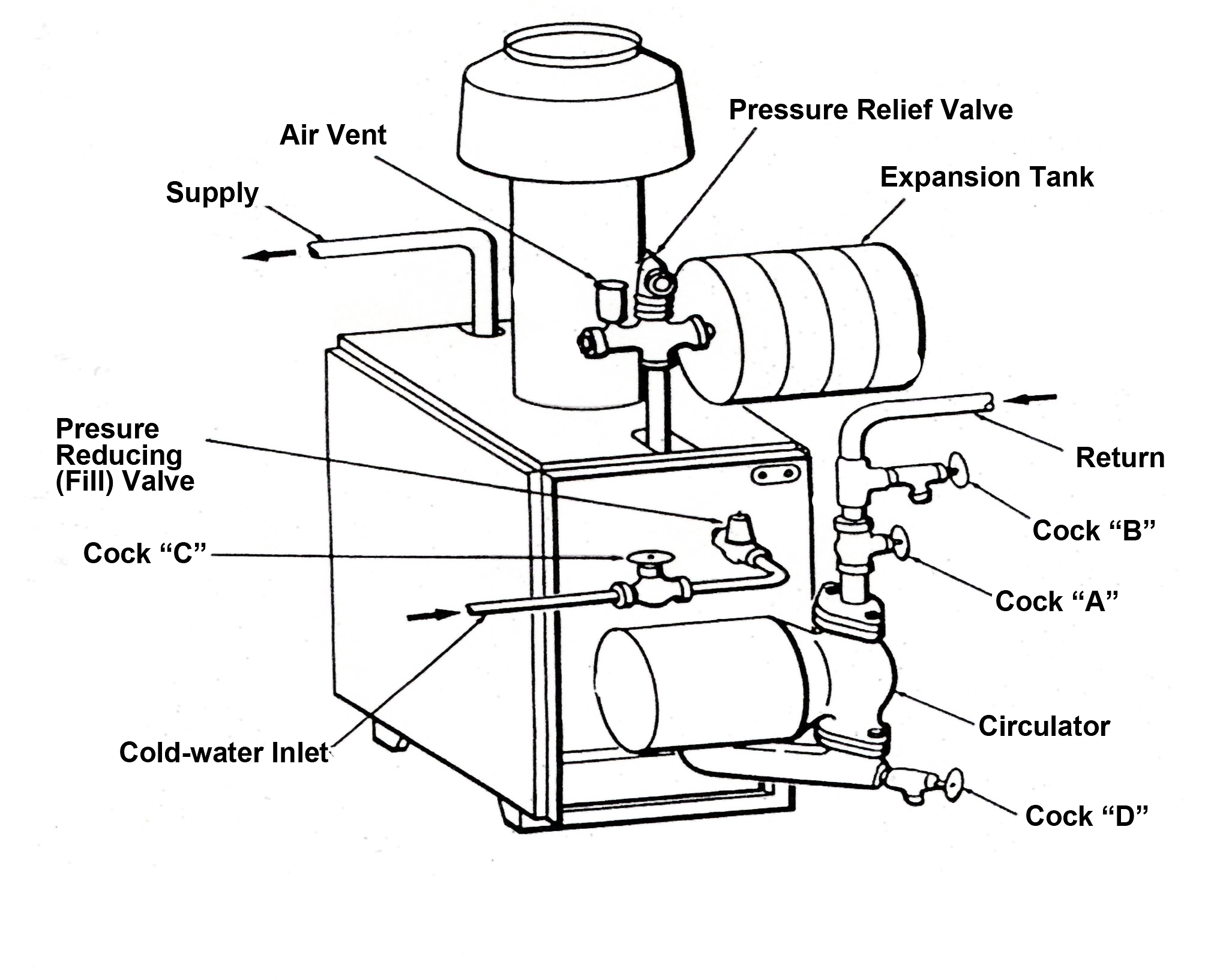
We will be emphasizing the older systems and not in this series get into Modulating/Condensing equipment. I want to address controls that are unique to gas. Below is an example of a typical gas package boiler of the 1950s still used in the present.
Pumping Away
Systems work better when the compression tank is connected on the suction side of the pump. This is called the “Point of No Pressure Change.” This is the way commercial systems have been installed for years. This typically means that the circulator is installed pumping away from the boiler and toward the systems.
The idea has in recent years caught on with residential and small commercial piping. It was probably not done in the past because no one ever gave people a good reason to change, but now there is a good reason. Just look at all the changes that circulators have gone through over the past few years. These new circulators are smaller and run at higher speeds and higher heads.
That makes a difference in the way the system operates. We have seen so much of a difference, in fact, that we see a brand-new opportunity for you.
When a circulator pumps away from a compression tank (expansion tank), all the circulator’s pressure appears as an increase out in the system. This sudden increase in pressure helps move air out of the radiators. Start-up becomes much easier, and, usually, there are fewer air-related problems from that day on.
On the other hand, when you pump toward a compression tank (typically, when the pump is on the return side of the boiler), the circulator’s pressure appears as a drop in pressure on the circulator’s inlet side.
If you’ve ever piped a feed valve into the inlet side of a circulator on the return side of a boiler, you’ve seen this drop in pressure. The feed valve opens every time the circulator comes on. It can be a real problem.
This sudden drop in system pressure also makes it harder to get the air out of the radiators. System start-up is tougher (especially on one-pipe systems with venturi-type fittings) and, in some cases, air can actually be sucked into the system through the air vents.
No one really noticed this problem with the older circulators, but nowadays, many residential systems are using small, high-speed circulators. These circulators, because of the higher heads they produce, can help you remove system air—if you install them pumping away from the compression tank and toward the system, or they can work against you.
When you install them pumping toward the compression tank, they will drop the system pressure on their inlet side (as much as six psig) every time they come on. That sudden drop in pressure will expand the trapped air bubbles up in the radiators, making it even more difficult to get air out of the system.
Have you ever noticed how it always seems to be those last couple of convectors, the ones closest to the return, which give you the biggest problem on start-up? Now you know why.
Why not use this pressure phenomenon to your advantage? Pump the supply side. The system will work a lot better and you may be amazed at the results. We say this even as we recognize that pumps installed on the return side have worked for years. They’ve even become a tradition. Most of the drawings published over the years show the pumps on the return side and with the low-head pumps, this usually is not a problem. However in light of today’s high-head circulators, we’ve become convinced that your systems will work much better and start up a lot easier if you take this fresh approach of pumping away. It’s good to question habit and tradition from time to time.
Some examples are illustrated:
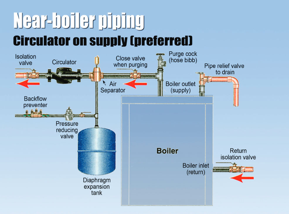
Below is an example of pumping away with circulator on the supply side, which is the preferred method. The circulator can however be placed on the return and still allow for pumping away from point of no pressure change.
Control Systems
As we go over different controls, all of them will fall into some category of what part of the system they function in or control. This is an example of some that in particular are used in hydronic systems in particular. The listing includes controls also used on forced warm air so that we may have some point of reference.
1. Primary Controls (loads)
A. Is the control that is being controlled by the thermostat or controller.
B. Require power for their operation in:
(1) Gas Valves
(2) Relays
(3) Zone Valves
(4) Zone Dampers
(5) Flue Dampers
2. Operators (operate primary controls) (switches)
A. Thermostat
B. Aquastat
C. Pressuretrol
3. Secondary Controls
A. Pressuretrol (2 lbs off .5 lb on (steam) (hot water
and steam)
B. Low water cut off
C. High limit (warm air) (200°F)
D. High limit (hot water)
E. Low limit
F. Fan Control Normally Open (Closes on a
temperature rise)
G. Reverse acting control (pump aquastat, circulator
control)
4. Loads
A. Relay coil
B. Motors
C. Transformers (primary load) (secondary source)
When it comes to setting temperatures for forced hot water conventional systems, the Incorporation by Reference (IBR) handbook suggest settings follow.
Settings for different systems
STEAM: Pressuretrol: 2 lbs. off–.5 lb. on (on normal household jobs)
VAPOR: Vaporstat: 8 oz. off–2 oz. on (unless engineer gives different setting)
FORCED WARM AIR: Combination fan and limit control
Limit: 200°
Fan on: 125°
Fan off: 110°
(if separate controls, set accordingly)
GRAVITY WARM AIR: Airstat Limit
control: 250°
GRAVITY HOT WATER: Aquastat Limit
control: 140°–150°
FORCED HOT WATER: High Limit control: 185°
(for radiators) 200° (for convectors)
210°–215° (baseboard radiation)
Low limit control: 150°
Circulator control: 120°–125°
(If there is a combination control with low limit and
reverse on the same setting, set the low limit to 150°and the differential to 25°).
AUXILLARY LIMITS
STEAM: Pressuretrol: 2 lbs off–.5 lb on.
Auxiliary pressuretrol:14 lbs off–
(set cut in to nine and differential to five) 9 lbs on.
HOT WATER: High limit 180°
Auxiliary high limit 220°
Thanks to Dan Holohan for the information on pumping away. Contact him at HeatingHelp.com.