Written on: August 12, 2012 by George Carey
There are many formulas and equations that make up the underpinnings of a properly operating hydronic system. There is one in particular that once understood, allows you to “see” what’s going on in any hydronic system.
Flow in a hot water heating system is used to carry heat from the boiler room out to the system. An accurate load calculation is the basis for any system design. The following formula is used to calculate the required flow in any hydronic system:

You will notice in the formula being used that the specific heat and density are referenced to 60°F water. But since 60°F water is too cool for a typical heating system and too warm for a typical cooling system, you would think that the flow should be calculated by taking into account the following changes:
• Specific heat and density changes caused by water temperature changes.
• Volume flow changes between the supply and return pipes due to temperature differences between them.
The effect of these changes can be evaluated in physical properties on heat conveyance of water by determining the net change in heat conveyance as system temperature rises.
The formula we use to determine system flow rate assumes a mass flow rate of 500lbs. per hour for each gpm, which means at a 20° T, 1 gpm will convey 10,000 BTUH (500 x 20) referenced to 60°F water.
What happens to the heat conveyance of 1 gpm @ 20°F T when the circulated water has an average temperature of 200°F? Water at 200°F has a density of 8.04 lb/gallon instead of 8.33 as at 60°F; however, its specific heat goes up to 1.003 from 1.0 as at 60°F. The heat conveyance for 1 gpm at 20° T will then be:
8.04 x 60 x 1.003 x 20 =9677 BTUH
The net effect is not significant in itself, but there is another factor that needs to be considered for a complete evaluation. As water temperature rises, it becomes less viscous, and therefore its pressure drop is reduced. When water is circulated at 200°F, the corresponding pressure drop or “head loss” is about 80% of water at 60°F for typical small hydronic systems. When calculated using a system curve, the flow increases by about 10.5% .
Now you can multiply the new heat conveyance just calculated by the percentage of flow increase: 1.105 x 9,677=10,693 BTUH. As you can see, with regards to heat conveyance, the simple “round number” approach will result in design flows very close to the “temperature corrected” flows, providing the results from the “round number” approach isn’t corrected from the original 60°F base for both the heat conveyance and piping pressure drop. The plus and minus factors very closely offset one another.
So you see that GPM can play a major role in ensuring that your heating system performs as expected. You need the right size circulator to be able to move the heat from the boiler and deliver it out to the terminal units where this heat is needed. In selecting the proper circulator, not only do you need to know the correct GPM, you also need to know the required pressure drop in feet of head to pump the necessary GPM.
As water flows through the piping network and radiation, it “rubs” against the pipe wall, causing fric-tional resistance. This resistance can impact the performance of the heating system by reducing the necessary GPM from circulating throughout the piping network. By knowing what this resistance will be, you can select a circulator that has the right feet of head to overcome this system’s pressure drop. Typically in today’s systems, we use feet of head to describe the amount of energy needed to have so that the required GPM is delivered out to the system. There are pipe sizing charts that have calculated the pressure drop in foot head of energy loss for any flow rate through any size pipe. Of course, there are standard piping practices that limit the amount of GPM for a given pipe size.
There are two reasons:
1. Velocity concerns—the speed at which the water is moving inside the pipe can create noise problems and, in extreme conditions, erosion problems.
2. The required head loss can become so excessive that the required circulator’s head capacity makes for a very “unfriendly” system selection, which can lead to control valve and velocity noise problems. The industry standard is to select a pipe which offers the frictional resistance between 1’–4′ for every 100′ of piping.
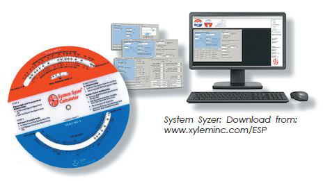 Bell & Gossett has provided a tool for the hydronics industry for over 50 years called The System Syzer. This tool is very useful in calculating GPM, what size pipe to use, as well as the corresponding pressure drop (head loss) for any application. It comes in a couple of formats—the original is a plastic wheel which is available form your local B&G Representative— but they also have a version available online for Windows PC and laptops: www.xyleminc.com/ESP. Just click on the System Syzer when you get to the link and you can download it.
[Editor’s note: Xylem says the newest iteration, System Syzer Version 4, is now available. System Syzer Psychrometry, available for cooling coil applications, is also available from the same website.]
If you have any questions or comments please call me at 1-800-423-7187 or email me at gcarey@fiainc.com.