Written on: June 2, 2025 by Timmie McElwain
There are some applications where a single furnace cannot deliver enough BTUs or CFM to heat a space. When these applications arise, a simple solution may be to put in two furnaces and “twin” them together. This allows both furnaces to operate off of one thermostat and be tied into a single duct system.
There are some simple rules that need to be followed to accomplish this:

It is in error to assume that the blower capacity is “additive.” When furnaces are twinned, the combined blower capacity is only 85% of the total CFM produced by the two blowers. Where this becomes a problem is when contractors think that since they have two five-ton blowers, they can put a 10-ton air conditioner on them. Since the capacity is reduced 15% when twinned, those two five-ton blowers will only be able to deliver 3400 CFM—enough for a seven-and-a-half-ton application.
Twinning permits two furnaces (see Figure 1) to operate as a single unit on the same ductwork. It is often necessary when the required BTU of the old furnace can’t be satisfied by one furnace. For example, when an existing 150,000 BTU furnace needs to be replaced, there is no residential furnace of that size currently manufactured, so two 75,000 BTU units can be used.
The Duct System
Twinned furnaces must only be applied on a common duct system. A single air supply plenum must be used for both furnaces and coil(s). Separate plenums and supply ducts systems cannot be utilized.
A single return air plenum common to both furnaces must be used. It is suggested that a return platform be utilized, with bottom air entrance into each furnace. If a side entrance return system is used, the common return duct must be divided equally so as to supply each furnace with an equal amount of return air.
Both furnaces must be identical models in both heating capacity and CFM capacity. As well, both furnaces must be operated on the same motor speed tap. The cooling speed connection is used for all heating, cooling and “Fan Only” operation. See Figure 2 for the typical application.
Note that when two furnaces are twinned, typical system total airflow will be approximately 85% of additive individual furnaces, i.e., two 2000 CFM units will yield a total 3400 CFM.
WARNING: If a return duct is connected to only one furnace (with a connection between the two furnaces), an imbalance in the air flow will occur and the furnace furthest from the return plenum will overheat.


Twinning Kit NAHA003WK01
Twinning kit NAHA003WK01 is for use with furnace models using Honeywell ST9120 or Heatcraft FCC Electronic Fan Controls. The kit is intended to permit two identical gas furnaces to be installed connected to the same duct work. Air conditioning can be added by using one air conditioning evaporator coil sized for the total air flow capabilities of the two furnaces.
Single & Two Stage Heating
Single or two stage heating may be obtained using twinning kit NAHA003WK01. Follow the instructions located in the Twinning Kit Installation section for proper hookup of desired thermostat staging.
Furnace Installation
Refer to the installation instructions packed with the furnaces for information about clearances, start-up and maintenance, gas piping and vent installation.
CAUTION:
Note: Once the twinning kit has been installed, locate the adhesive backed wiring diagram included in the kit and apply next to the existing wiring diagrams in the furnaces.
Twinning Kit Installation
The twinning kit contains two 36″ wires of two different colors to interconnect the electronic fan controls of the two furnaces. For proper operation, and to avoid damage to the controls, be sure to match Z1 to Z1 and Z2 to Z2 on each fan control (see Figure 5). The wires are color-coded to assist with this connection. Each wire is factory terminated with a special crimped edge connector, which will push into mating connection positions on the edge of the circuit board on each fan control. Cutting and splicing sufficient additional wire to each lead can extend the length of these wires. An isolation relay is provided to protect the system’s thermostat from possible overloading due to the combined valve and control load of the two appliances.
The installation procedures are as follows:
1. Remove line power from both appliances before starting installation of the twinning kit.
2. Locate the Z1 and Z2 connections along one edge of each control (see Figure 5). The designations are printed on top of the circuit board and a black bar shows the correct orientation of the metal body, which will be pushed in to make connection.
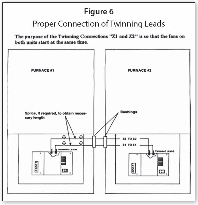
3. Remove furnace casing hole plugs and route the twinning leads through bushings provided as required, and lengthen if necessary by splicing. Be sure to observe the polarity required so as to match Z1 to Z1 and Z2 to Z2 (see Figure 6).
4. Push the terminal into the slot on the circuit board edge. Be sure to align the body with the black bar to line up the solder finger below the circuit board (see Figure 5). The terminal will “bite into” the solder and make the necessary connection. Repeat for each end of both wires.
5. Locate and mount the isolation relay in the circulating blower compartment on the same panel as the electronic fan control in furnace #1 (see Figure 1).
6. Refer to single stage or two-stage thermostat wiring as noted below.
Single Stage Thermostat Operation
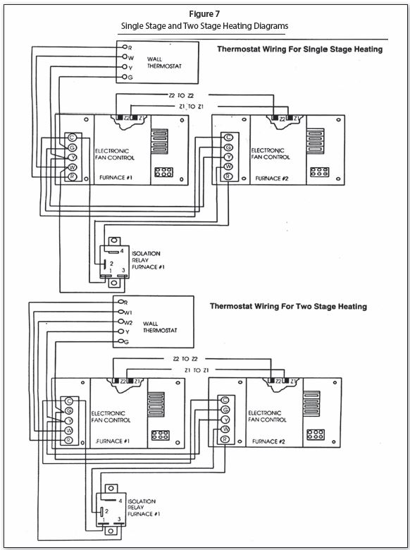
Reference Figure 7 for the below:
1. Interconnect the thermostat wiring in parallel from the thermostat to the terminal blocks on each fan control, for the “G” and “Y” connections only. Interconnect the wiring from the “C” connections at the terminal blocks on each fan control. Note: The “Y” connection is not required if air conditioning is not available.
2. Connect wire from “W” connection at the thermostat to the “W” connection of the electronic fan control of furnace #1.
3. Connect wire from “R” connection at the thermostat to the “R” connection of the electronic fan control of furnace #1.
4. Connect wire from the “W” connection of the electronic fan control of furnace #1 to one side of the 24Vac coil of the isolation relay (terminal #3). (Wire terminals for connection to the isolation relay are provided in the kit.)
5. Connect wire from the “C” connection of the electronic fan control of furnace #1 to the other side of the 24Vac coil of the isolation relay (terminal #1).
6. Connect one wire to each of the normally open terminals of the isolation relay (terminals #2 and #4) and connect to the “R” and “W” connections at the electronic fan control of furnace #2. Set the heat delay off timings on each control to the same setting.
7. Set thermostat anticipator setting at 0.90.
8. Recheck wiring connections, splices and insulation. Re-apply line power to both appliances.
Two Stage Thermostat Operations
Reference Figure 7 for the below:
1. Interconnect the thermostat wiring in parallel from the thermostat to the terminal blocks on each fan control, for the “G” and “Y” connections only. Interconnect the wiring from the “C” connections at the terminal blocks on each fan control. Note: The “Y” connection is not required if air conditioning is not available.
2. Connect wire from “W1” of the thermostat to the “W” connection of the electronic fan control of furnace #1.
3. Connect wire from “W2” of the thermostat to one side of the 24 VAC coil of the isolation relay (terminal #3). (Wire terminals for connection to the isolation relay are provided in the kit.)
4. Connect wire from “R” connection at the thermostat to the “R” connection of the electronic fan control of furnace #1.
5. Connect wire from the “C” connection of the electronic fan control of furnace # 1 to the other side of the 24VAC coil of the isolation relay (terminal #1).
6. Connect one wire to each of the normally open terminals of the isolation relay (terminal #2 and #4) and connect to the “R” and “W” connections at the electronic fan control of furnace #2.
7. Set the Heat Delay Off timings on each control to the same setting.
8. Set thermostat anticipator setting at 0.75 for the first stage and 0.15 for the second stage.
9. Recheck wiring connections, splices and insulation. Re-apply line power to both appliances.
Twinning Kit Operation
1. Turn the heat/cool switching at the thermostat to “OFF,” or set so neither a call for heating nor cooling is being made.
2. Turn the fan switch to “ON” from “AUTO,” or jumper from “R” to “G” at “furnace 1.” Within several seconds, the circulation blowers of each furnace will start at the same speed connected to their respective “heat” speed taps.
3. Turn the fan switch to “OFF” from “AUTO” or remove the jumper from “R” to “G.” Both circulation blowers will stop after several seconds.
4. Disconnect one wire from the high limit connection on “furnace 1.” Within several seconds, the circulation blowers of each furnace will start at the same speed connected to their respective “heat” speed taps.
5. Re-connect the wire removed from the high limit connection on “furnace 1.” After the completion of the heating “blower off” delay, both blowers will stop.
6. Repeat Steps 4–5 with the limit connection in “furnace 2” versus “furnace 1.” The same operation should result.
7. Operate the system through a normal call for heat, burner ON operation and burner OFF operation. Each furnace should fire and cycle both blowers, including blower ON and OFF delays, as in a normal single system.
8. Operate the system through a normal call for cooling. The compressor operation should function normally; with each furnace circulation blower operating at the speeds connected to their respective “cool” speed taps after cooling “blower ON” delay. When the call for cooling ends, the circulation blowers will stop upon the completion of the “cooling off” delay.
The instructions covered above are for one particular model of furnace. It is important to follow the directions for the furnace model you are installing or servicing.
Another thing to consider is control replacement when an EFT board or Integrated Furnace Control Board fails. Different manufacturers’ boards are not typically compatible. When looking to future replacement, the exact board would have to be available or the twinning function will not work. It is a possibility that both furnaces would have to be replaced. Another concern is if one of the heat exchangers goes on furnace # 1 and it is 10 years old, for example, then probably both furnaces will have to be replaced.
Figures 5 thru 7 illustrate connections and wiring for twinning. ICM