Written on: February 12, 2024 by Timmie McElwain
As the gas industry has progressed, so have the requirements for electronic controls.
There are many setups that use rather sophisticated electronic controls to accomplish many of the functions required on systems today. Almost everything in modern-day homes uses some kind of microprocessor-type control.
The mandates for efficiency have pretty much driven the industry into the electronic age. We could probably still do some of the things we do with electromechanical controls, but it would be with great difficulty. These functions are much easier with microprocessor-type controls.
We will be discussing electronic controls used on furnaces and boilers. On the furnace side, we have electronic fan timers (EFTs) and integrated controls. On the boiler side, we have multi-zone panels and, specifically, integrated boiler controls.
Electronic Fan Timers
Electronic fan timers have been around a while. The ST9101 EFT is used on some standing pilot furnaces and the ST9103 is used on oil furnaces. The ST9103 EFT integrates control of burner and circulating fan operation in an oil furnace. The ST9101A; ST9120A-C, G; ST9141A integrates control of the combustion blower and circulating fan operation in gas warm air furnaces. The use of twinning on warm air systems today is also addressed by the twinning features on these controls. It is important to realize that these controls are configured for application to specific appliance models. They are intended for direct replacement of Original Equipment Manufacturer (OEM)-installed controls only as noted in the order table. Do not attempt to install these controls except as direct replacements for the specific Honeywell models noted in the order table.
We will also subsequently address the use of Universal Replacement Controls ST9120U-1003 and ST9120U-1011.
Figure 1 shows the ST9101A controls and the particular OEM they were used by. Later, as we address universal replacement controls, one can see that many of these are replaceable by a universal application.
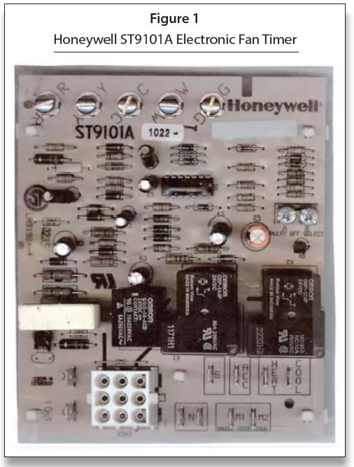
The ST9101A EFT integrates control of all combustion blower and circulating fan operations for a gas warm air appliance. The basic purposes of the ST9101A are to monitor the thermostat and run a combustion blower with a two-speed circulating fan. The ST9101A monitors the thermostat for heat, cool and fan demands. The ST9101A also monitors a limit switch string, energizing the circulating fan when any of the limits open.
The basic ST9101 EFT is used principally on Rheem standing pilot furnaces with induced draft blowers.
• Fan control delays
• Induced draft blower
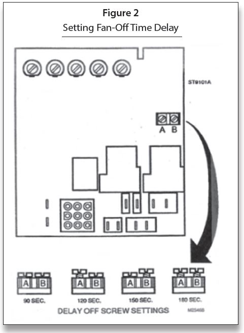
Usually the fan-ON time is fixed at either 30 or 60 seconds to meet the needs of a particular furnace, but the fan-OFF timing is adjustable to meet the needs of a particular application. This control from Honeywell is a set of screws that must be adjusted, as shown in Figure 2. The screw heads make contact between two wires to create an input to the electronic circuits.
Some models use a different EFT, such as a Robertshaw Model RBC-1 shown in Figure 3, as the adjustment for blower off delay using the jumper on the control board to the pins desired.

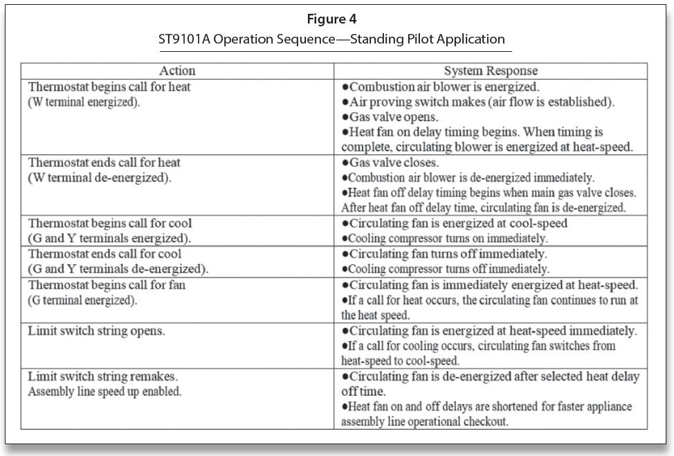
The operating sequence for the ST9101A is shown in Figure 4.
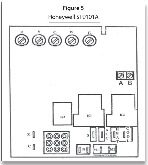
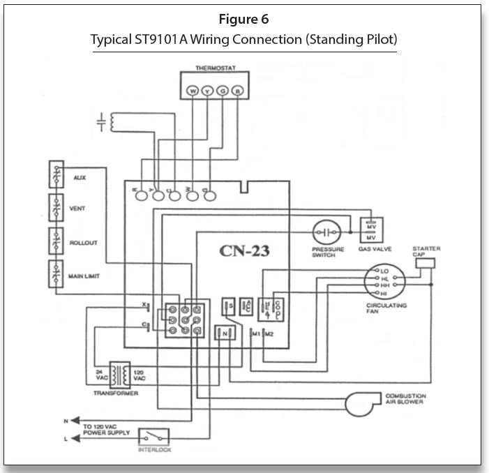
In the diagrams that follow, we will go through the sequence. In this step-by-step process, the pattern from various pins on the 9-pin connector labeled CN23 through the printed circuit board soldered connections will be followed. The schematic diagram shows those as dotted lines. The diagram fails to show the three relays used, so we will point them out as we trace the sequence. Figure 5 shows the various connections including the three relays labeled K1, K2 and K3. Figure 6 shows the CN23 pin numbers.
The schematic shown in the following drawings are a good example of a typical circuit used with EFTs.
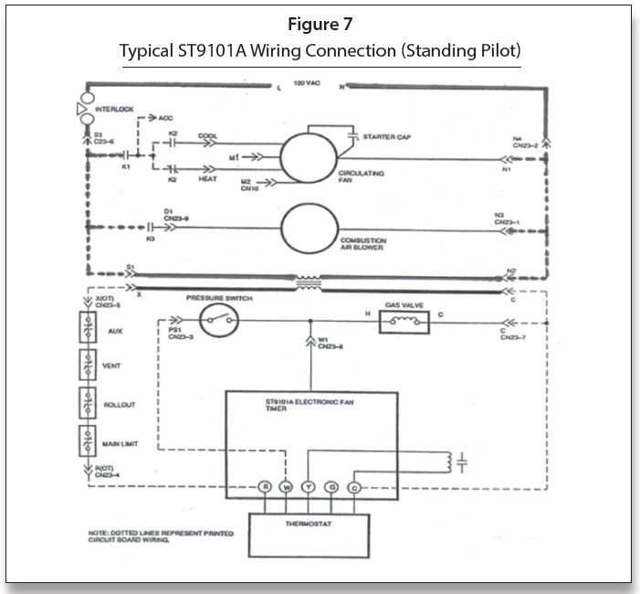
The initial circuit is the 120 VAC circuit from L through the interlock applying 120 VAC to S1 to N2 the transformer primary. This puts 24 VAC on the secondary side of the transformer, which is an external transformer. What actually happens is, out of the interlock, 120 VAC goes to S-3/CN23 pin 6 to N4/CN23 pin 2. From pin 6, 120 VAC goes through the printed circuit (dotted lines) to S1 then an external wire to the transformer then to N2 and back through the printed circuit board wiring to CN23 pin 2/N4 back to N (neutral). This is shown in Figure 7.
When there is a call for heat, as shown in Figure 8, from the thermostat “R” to “W” the circuit is from the transformer to “X” though the printed circuit to CN23 pin 5. Then to the auxiliary limit, blocked vent switch, rollout switch and main limit to CN23 pin 3 to the pressure switch. The pressure switch is in the normally open (NO) position and will not close until relay K3 is energized. When K3 is energized, it will cause the Combustion Air Blower to come on (120 VAC) DI CN23 pin 9 to N3 CN23 pin 1, this will pull in the pressure switch.
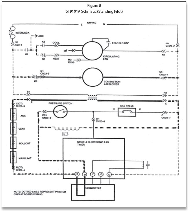
Figure 9 shows the pressure switch (now closed); the gas valve is energized H to C CN23 pin 7 back to “C” (common) on the transformer.
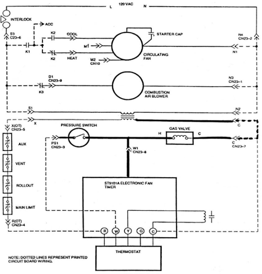
Figure 9
Figure 10 shows that there is also 24 volts fed to W1 CN23 pin 8, which starts the fan on delay timer to bring on the fan by energizing relay K1. This is turn causes switch K1 to close putting 120 VAC through relay switch K2 (set by putting the thermostat Heat/Cool switch on Heat).
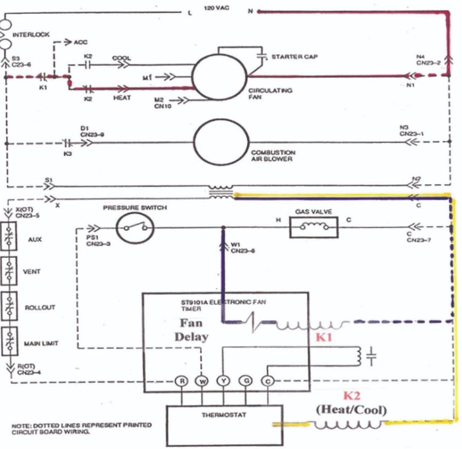
Figure 10
The system is now up and running. Figure 11 shows when the thermostat is satisfied “R” to “W” breaks de-energizing relay K3; this will shut down the Combustion Air Blower and the pressure switch will open. This will cause the gas valve to shut down and the fan-off delay will start as pre-set on the A & B screws for time.
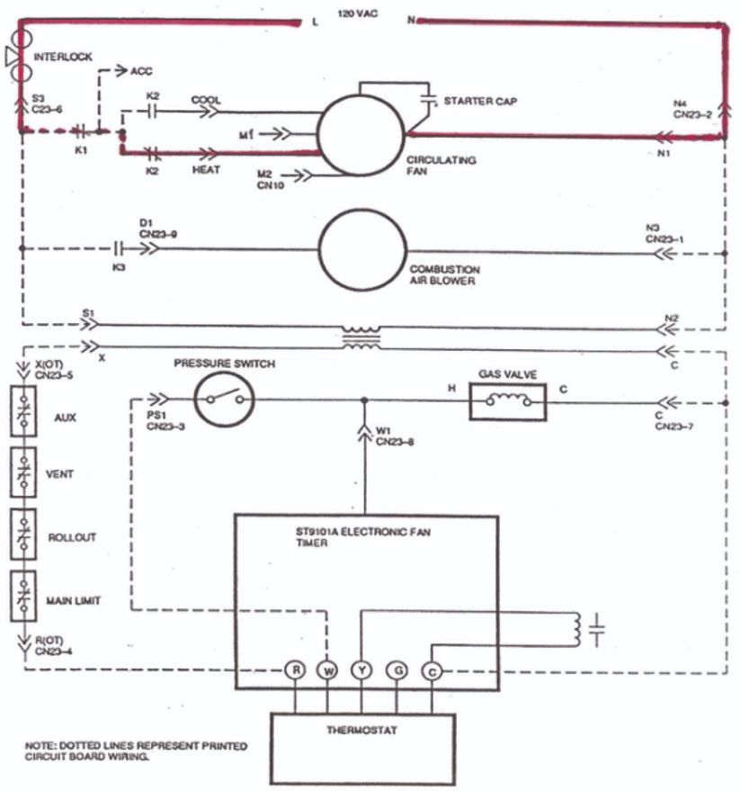
Figure 11
When the fan-off delay time is complete, the system will be totally shut down and waiting for the next call for heat.
Understanding this entire sequence can make the job of troubleshooting these systems much simpler. ICM