Written on: September 23, 2021 by Timmie McElwain
As we look into some more modern systems and what specific problems they present, it is important to understand the basic fundamentals associated with these systems. Most of our modern heating equipment in some way or another involves electronics, and with the electronics, the use of flame rectification as a safety and flame-proving system.
It does not matter if it is a forced warm air furnace or a forced hot water boiler—the same basic system is used to perform safe ignition followed by consistent operation throughout the entire call for heat.
There are, however, different ways the system is applied from intermittent pilot application to direct spark ignition and including hot surface ignition. Each has its own distinct advantages and problems. In this next series, we’ll attempt to resolve those burner problems related to these systems as well as offer corrections and diagnostics.
We will start with the basics and continue to operation, typical problems, diagnosis, troubleshooting procedures and hopefully a final solution to your particular problem. It’s easy to jump to conclusions with these systems and just change parts to hopefully solve the problem. That is, however, time consuming and costly.
I invite you to visit our new Facebook page Timmie’s Tips on Gas, it is located here. I look forward to seeing you there.
The Honeywell Smart Valve story
In this article, we are going to cover the Honeywell Smart Valve systems and discuss Generation I and Generation II. Generation I is obsolete, but controls from that series may still be in the field.
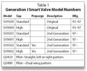
Smart Valve is the name Honeywell has given a unique ignition system developed in 1993. The Smart Valve combines all the best features of intermittent pilot ignition and hot surface ignition. It utilizes a pilot to light the main burner. It uses a glowing 24-Volt igniter to light the pilot light instead of a spark. There have been two Smart Valve systems. The first generation was manufactured from 1993–1997. Generation I included SV 9500, SV9501, 02 (0.5″ x 0.5″ pipe and 200,000 BTUs) and SV9600, SV9601, 02 (0.75″ x 0.75″ pipe and 415,000 BTUs). The new generation is still in production at the present time.
System controls & application
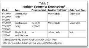
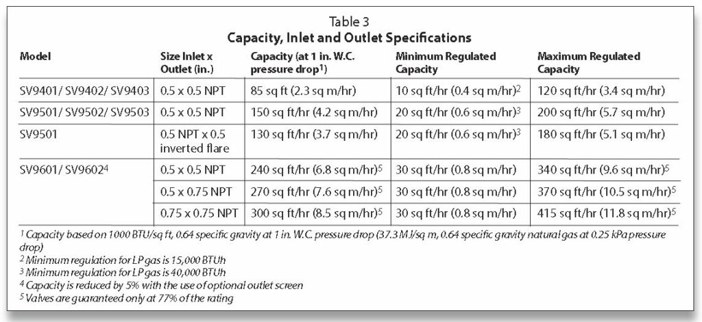
The SV9401/ SV9402/ SV9403, SV9501/ SV9502/SV9503 and SV9601/ SV9602 SmartValve System Controls combine gas flow control and electronic intermittent pilot sequencing functions into a single unit. This product family offers several different intermittent pilot sequences for a wide range of applications. See Table 2 for specific sequences available. The Q3450 or Q3480 intermittent pilot hardware provides low voltage ignition, flame sensor and pilot burner. This system is suitable for application in a wide range of gas-fired appliances including furnaces, rooftop furnaces, boilers, unit heaters, infrared heaters, space heaters, water heaters, decorative appliances and commercial cooking units. The specific application of the SmartValve System is the responsibility of the appliance manufacturer. See Table 3 for gas capacity and thread sizes.
The Tradeline SV9501 and SV9502 SmartValve models are replacement controls only for the SV9500, SV9501 and SV9502 models. Do not use these controls to replace other types of intermittent pilot or direct ignition controls. Do not use other controls to replace SmartValve models; the controls might fit, but the gas flow control functions might not be compatible with the appliance.
The Tradeline SV9602 SmartValve models are replacement controls only for the SV9500P, SV9501 P, SV9502P, SV9600P and SV9601 P models. The SV9602 is a prepurge, step-opening model.
1. Prepurge is normally 30 seconds.
2. The step-opening function provides a timed step outlet pressure at the start of each heating cycle to allow main burner ignition at reduced outlet pressure.
3. Reducer bushings are provided with the SV9602 and SV9601 models to adapt to smaller pipe sizes.
4. Ignition system controls with standard opening regulators (SV9501M, SV9502M and SV9601M) or slow opening regulators (SV9501 and SV9502H) can be converted between natural gas and liquefied petroleum (LP) gas.
5. Ignition system controls with step-opening regulators (P suffix) cannot be converted between gases.
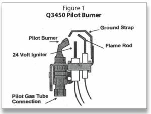
Pilot burners
The first difference you see is the pilot burner—a standard Honeywell burner similar to the Q314. What is unique is the ignition source for the pilot:
• Small igniter in front of the pilot
• Powered by 24 Volts
• Glows red hot on a call for heat to light the pilot.
The igniter is made of silicon nitride, which is similar to the material used for hot surface igniters. It is, however, stronger and is well-protected by the pilot burner and ground strap so that it does not break unless it receives unusual abuse. The igniter has a positive coefficient with a relatively low resistance when cool. Therefore, the initial current flow makes it heat up very fast. The pilot usually lights in a few seconds. The flame rod is positioned to “prove” the pilot. Flame rectification is used to prove the pilot flame is burning. When the flame is detected the igniter is turned off. The main valve opens. Flame rectification provides fast, sensitive flame detection.
The igniter flame rod assembly is replaceable without having to replace the entire pilot, which is a great advantage over intermittent pilot systems. The original pilot and harness that plugs into the valve (Part No. Q3400A-1024) was an unshielded version. A shielded version (Part No. Q3400A-1115) was released due to problems with pinching the cables and getting a feed over of 24 Volts on the microamp wire. The blue wires on the harness are for 24 Volts to get the igniter to glow. The first versions had a clear wire, which was for the microamp signal back to the electronics on the valve. It was later changed to a black wire. The Generation I valves used 24 Volts as a superimposed signal and they had a minimum microamp signal of .3 microamps. Generation II uses 80 + Volts to create a minimum signal of 1.3 microamps.
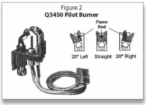
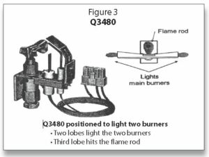
The pilots are the Q3450 (Figure 1 and Figure 2), which is a lower input pilot, and the Q3480 (Figure 3) version, which has a little higher input.
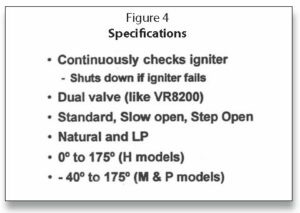
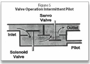
The Smart Valve is a dual valve (redundant) valve based on the VR8200 and VR8300 series of gas valves. The dual valve feature guards against the possibility of a passing gas valve. The capacity goes all the way up to 415 cubic feet per hour and has a 1″ W.C. pressure drop at 300 CFH.
Figure 5 shows that the first valve is a solenoid valve, which opens upward and is actually the PV (pilot valve). It is designed in such a way that if pressure in excess of 14″ W.C. is applied to the valve, it may not open. This is a safety feature to prevent over-pressure and possible damage to the diaphragm valve. The second valve is the servo valve (a diaphragm valve controlled by the servo regulator); it is typically the MV (main valve). The second servo valve will not be powered until the flame is proven by rectification.
There are various models available to manufacturers:
• Standard open (M model)
• Slow open (H model)
• Step open (P model)
The M and P models are rated for -40°F so they can be used on rooftop units or other unheated spaces. Replacements for many models can be found in the Honeywell Tradeline catalog or at customer.honeywell.com.
The valves can be used with natural or LP gases. The exception is the P model (step opening), which can’t be converted. There are conversion kits available:
• Natural to LP 393691
• LP to Natural 394588
There are also pilot orifices available for the Q3450 pilot:
• Natural BCR18 (.018)
• LP BBR 11 (.011)
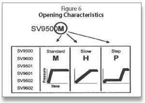
Figure 6 illustrates the different opening characteristics of SmartValve Standard open valve:
• Fast open
• Reaches full rate in 1–2 seconds, depending on capacity
• On some applications, particularly low firing rates, there is little variation in regulation for a half second when it first turns on
Slow open valve
• Takes about 4–5 seconds to get fully open
• Under maximum capacity, it may even take 9–10 seconds to get fully open
• Again, for service, replace with slow open
Step open
• Valve opens to some fixed (non-adjustable) low rate for light-off, and after 10 seconds, goes to full rate
• For service work, replace with step opening only as there may be ignition problems with any other opening characteristic
• Equipment manufacturers chose step open (at higher cost) for a reason
• Usually used to make light-off smoother or to cure light-off problems
When the Smart Valve receives a call for heat, there is an immediate surge of current due to the low resistance through the igniter (low cold resistance). Silicon nitride has a positive temperature coefficient. Line voltage igniters have a negative temperature coefficient. The hot resistance is high. There is a 22.5 Volt drop across the igniter and a 1.5 Volt drop across the pilot valve relay coil. The pilot valve relay coil is immediately energized, pulling in the pilot valve. On the original Generation I Smart Valve there was continuous trail for ignition—the igniter came on and stayed on until the system lit off. Generation II has continuous retry with a 90-second trial for ignition followed by a 5-minute wait period if ignition does not take place.
During the 90-second attempt at ignition, the igniter will be on for 30 seconds, then shut off for 25 seconds, then back on for 30 seconds. This is to keep from overheating the pilot relay and to extend the life of the igniter.
SV9501 (Generation II) features
The new features of Generation II of the Smart Valve include:
• Meeting new Z21.20 requirements
• Switch provides manual shutoff
• Soft element warm up
For direct replacement for the SV9500, or Generation I, you should be aware of the following:

• Same package shape and size
• Same Q3450 pilot burner
• Identical connectors (power connector on top)
The steps for the Call for Heat are as follows:
• Start check (three seconds)
• Trial for ignition (90 seconds)
• Pilot valve open
• HSI on (30 seconds)
• HSI off (25 seconds)
• HSI on (30 seconds)
• Pilot valve closed /HSI off
• Retry delay (five minutes)
• Trial for ignition
• Retry delay
• Cycle continues until pilot lights/proves or the call for heat ends.
For theQ3450 & Q3480 pilots, the pilot igniter and flame rod assembly on both the Q3450 and the Q3480 need to be field replaced. Figure 7 gives an illustration for doing so. The directions are as follows:
Replace Igniter-Flame Rod Assembly
1. Turn off the furnace at the circuit breaker or fuse box.
2. Remove the spring clip, then the igniter-flame rod assembly from the pilot burner.
3. Disconnect the igniter-flame rod assembly keyed plug from the igniter connection on the SV9500/SV9600.
4. Remove the igniter-flame rod assembly from the furnace.
5. Install replacement igniter-flame rod assembly in the pilot burner and secure it with the spring clip.
6. Connect igniter-flame rod assembly keyed plug to igniter connection on the SV9500/SV9600.
7. Turn on power and set the thermostat to call for heat. The pilot should light and then the main burner should lights.
Note: Sensor tip must be in pilot flame.
Adjust Pilot Flame
The pilot flame should envelop approximately 3/8″ (10mm) of the sensor tip.
To adjust pilot flame:
1. Turn off system by setting thermostat below the temperature to call for heat.
2. Disconnect lead to MV terminal on SV9500/SV9600.
3. Light pilot by setting the thermostat to call for heat.
4. Remove pilot adjustment cover screw from gas control.
5. Turn inner pilot adjustment screw clockwise to decrease or counterclockwise to increase pilot flame.
6. Always replace pilot adjustment cover screw and tighten firmly after completing adjustment to assure proper operation.
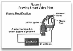
The Generation I system used a 24 Volt signal for rectification and had a minimum microamp signal of 0.3 microamps, which proved to be somewhat of a problem as it was too low and caused some nuisance shut-downs. Generation II went to a minimum voltage signal of 80+ Volts with a minimum microamp signal of 1.3 microamps. The flame-proving circuit is illustrated in Figure 8. A complete discussion on flame rectification is in our manual Electric Ignition Systems Volume I.
Figures 9, 10, 11 and 12 illustrate the physical differences between Generation I and II. The SV9500 with the on/off knob easily distinguishes it from the Generation II SV9501 and SV9502. In addition to the Generation II having a switch, the control harness connector was moved from the side to the top. Also shown is the use of the flange kit, which makes for ease when replacing a valve, as the 9/64″ hex screws and the valve can be easily removed by using a wrench to unmake the threaded portion of the valves.
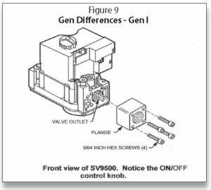
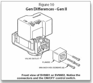
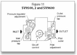
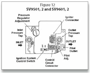
Figure 11 and Figure 12 also shows other typical characteristics of the valves, such as the pressure regulator adjustment, pilot outlet, inlet and outlet pressure taps for testing gas pressures with a manometer. The electrical connections visible on Generation II on top of the valve are the igniter connector and the control circuit connector.
Part 2 (From Indoor Comfort, Sep/Oct 2021)
Honeywell SmartValve
In this article, we continue our discussion of the Honeywell SmartValve. SmartValve is the name Honeywell gave a unique ignition system developed in 1993. The SmartValve combines all the best features of intermittent pilot ignition and hot surface ignition. It utilizes a pilot to light the main burner and a glowing 24-Volt igniter to light the pilot instead of a spark.
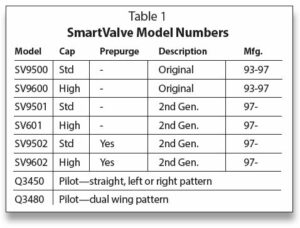
There have been two SmartValve systems. The first generation was manufactured from 1993–1997. The new generation is currently still in production. Generation I includes SV9500 and SV9501, 02 (1/2″ x 1/2″ pipe; 200,000 BTUs), as well as SV9600, SV9601, 02 (3/4″ x 3/4″ pipe; 415,000 BTUs).
Picking up where we left off in “The Gas Side—Honeywell Gas Valves: Part 1” in ICM’s July/August 2021 issue, here are directions for Standard Pressure Regulator (M Models), Slow Open (H Models, Step Open [P Models]):
1. Check the full rate manifold pressure listed on the appliance nameplate. The ignition system control outlet pressure must match the full rate pressure listed on the nameplate. Adjust the pressure if they do not match. Note: Slow opening (H models) and step opening (P models) may take several seconds to reach full flow rate. M models will take 2–3 seconds to reach full flow rate.
2. With the main burner On, check the ignition system control flow rate using the meter clocking method, or check the pressure using a manometer connected to the outlet pressure tap on the ignition system control.
3. Adjust the pressure regulator to match the appliance rating if necessary. See Table 2 and Table 3 for factory set nominal outlet pressure and adjustment range.
a. Remove the pressure regulator adjustment cap screw.
b. Using a screwdriver, turn the inner adjustment screw clockwise to increase or counter- clockwise to decrease gas pressure to the burner.
c. Replace the cap screw and tighten it firmly to prevent gas leakage.
4. If the desired outlet pressure or flow rate cannot be achieved by adjusting the ignition system control, check the ignition system control inlet pressure using a manometer at the ignition system control inlet pressure tap.
5. If the inlet pressure is in the factory-specified nominal range, as shown in Table 2 and Table 3, the ignition system control.
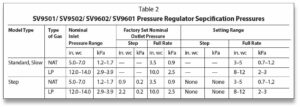
Otherwise, take the necessary steps to provide proper gas pressure to the control. Note: If the burner firing rate is above the maximum capacity as shown in Table 3, it might not be possible to deliver the desired outlet pressure. This is an application issue, not a control failure. Take whatever steps are necessary to correct the situation.

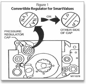
Convertible (Natural/LP) Regulator for Mobile Home Applications
Ignition system controls with the suffix letter R are convertible pressure regulator models. They can be converted from natural gas to liquid propane (LP), or from LP to natural gas, without a conversion kit.
Before converting the ignition control from one gas to another, check the ignition control label and the appliance manufacturer rating plate to determine if the factory-set pressure regulator setting meets the appliance manifold requirements after conversion.
Note: Convertible pressure regulator models (suffix letter R) do not have field-adjustable regulators.
If the factory pressure regulator setting meets the appliance manifold requirement, convert the ignition control using the following procedure:
1. Remove the pressure regulator cap (see Figure 1).
2. Turn over the cap so the letters facing up are for the gas type the appliance uses—NAT for natural gas and LP for liquid propane gas.
3. Replace the cap and tighten firmly.
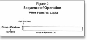
The original SmartValve had continuous trial for pilot ignition; the igniter and pilot gas would remain on indefinitely as illustrated in Figure 2.
SmartValve Generation II is a continuous retry version. It attempts to ignite with the igniter on and pilot gas flowing for 90 seconds. If there is not any ignition, then the igniter and pilot gas will shut down for five minutes. This is shown in Figure 3. The system will continue this sequence until ignition takes place or the power is shut off. There is not enough gas escaping during the try for ignition to reach the lower explosive limit of either natural or LP gases.
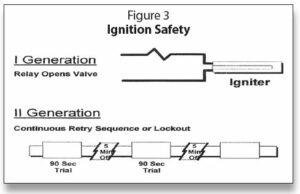
There is safety designed into the circuits, as the igniter is part of the valve control circuit. If the igniter is broken or otherwise electrically open, the valves cannot be opened; it is fail- safe.
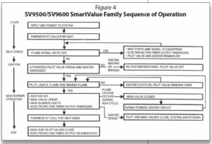
Figure 4 is the sequence of operation for the older Generation I system. Depending on the version, there may be a different sequence of operation with Generation II as shown in Figure 5.
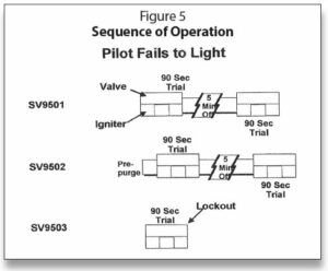
The SV9501 is the regular 90-second trial with the five-minute shutdown. The SV9502 will have the same trial times but will add prepurge at the beginning.
The SV9503 version is a single try with immediate hard lockout if ignition does not take place on the first try. This will require shutting the power off and reattempting another try for ignition. This system is used on many decorative fireplaces that use a switch on the wall to start the fireplace.
The sequence of operation illustrated in Figure 6 on a call for heat is that the pilot valve and igniter come on together when the thermostat calls for heat. The main burner opens only when the pilot is proved and remains open throughout the call for heat. The pilot burner also stays on during the entire call for heat. When the thermostat is satisfied, the pilot and main burner gas is shut off.
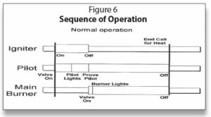
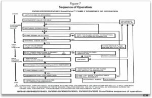
Figure 7 is the sequence of operation for the Generation II SmartValves.
In the next series, we will explore SmartValve’s typical wiring. ICM
Timmie M. McElwain is President of Gas Appliance Service, which provides training for those servicing gas combustion equipment. He is a certified instructor and test proctor for the Propane Gas Association in their CETP program.